
Fabricated beam-column connecting joint

A beam-column connection and assembly technology, applied in the direction of construction and building structure, can solve the problems of waste of steel bars, time-consuming and labor-intensive construction, hidden dangers of safety and quality, etc. Improve the effect of construction safety

Pending Publication Date: 2018-07-13
BEIJING ZHIHUI YUNJIAN TECH CO LTD
View PDF0 Cites 4 Cited by
  • Summary
  • Abstract
  • Description
  • Claims
  • Application Information

AI Technical Summary

Problems solved by technology

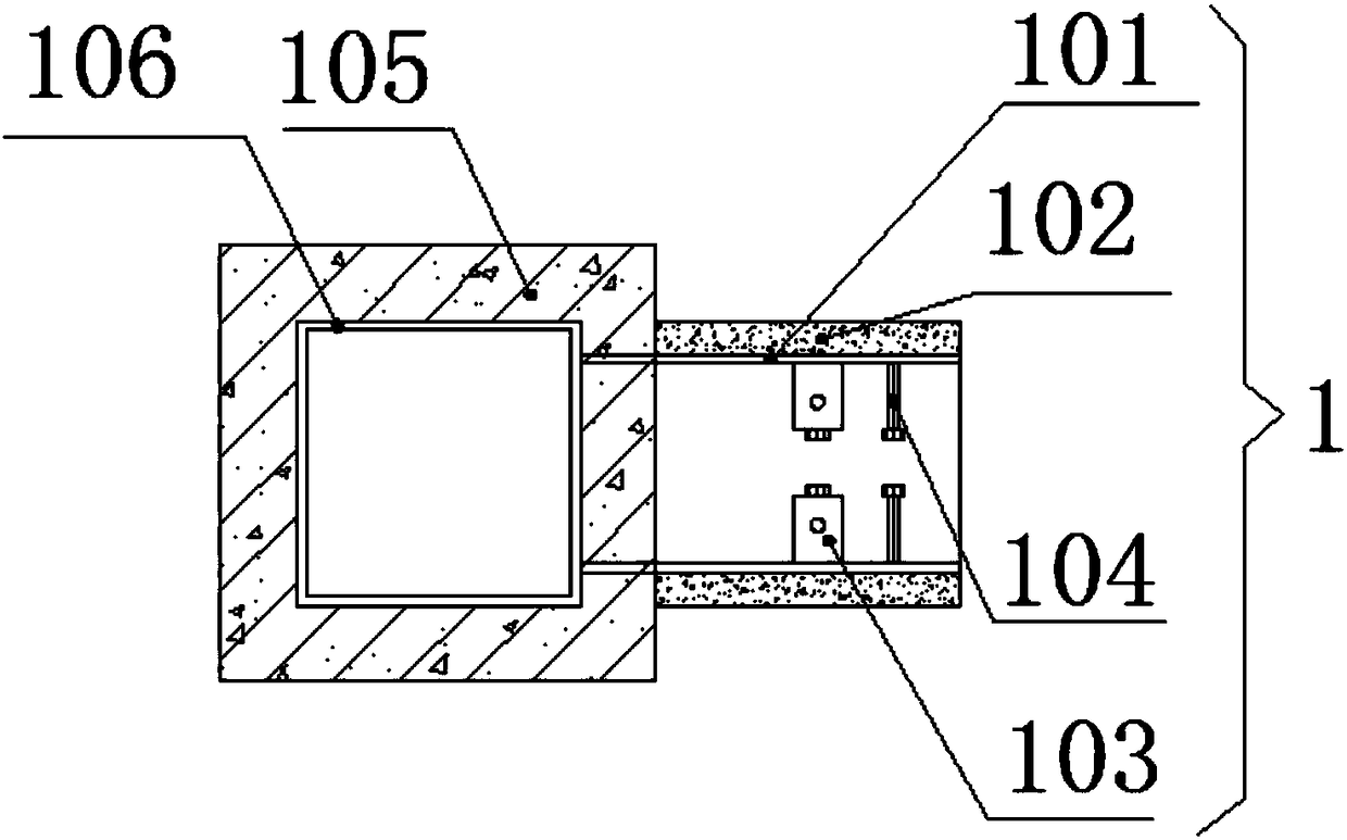
[0010] The purpose of the present invention is to solve the traditional prefabricated beam-column joints in the prior art where formwork needs to be manually supported and then concrete is poured. Formwork support at the joints is a major problem, which is time-consuming and labor-intensive and extremely difficult to construct. The appearance is not guaranteed; the traditional PC prefabricated beam-column connection adopts mechanical sleeve grouting connection, which requires precise alignment of the steel bars protruding from the beam end and the protruding steel bars at the column joints, which is difficult in actual operation and has hidden safety and quality risks; steel bar welding connection The welding machine needs to be transported to the installation floor, and the quality of the weld seam is difficult to control during the welding process; the overlapping connection of steel bars wastes steel bars, resulting in increased costs and difficult construction; Formwork support and concrete pouring are limited by the working surface and working environment, and it is difficult to guarantee the quality, appearance and poor operation. A prefabricated beam-column connection node is proposed.

Method used


Image

  • Fabricated beam-column connecting joint
  • Fabricated beam-column connecting joint
  • Fabricated beam-column connecting joint

Examples


Embodiment Construction

[0036] The following will clearly and completely describe the technical solutions in the embodiments of the present invention with reference to the accompanying drawings in the embodiments of the present invention. Obviously, the described embodiments are only some, not all, embodiments of the present invention.

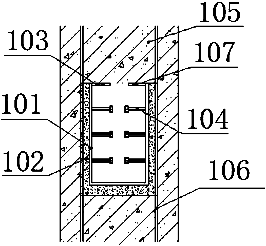
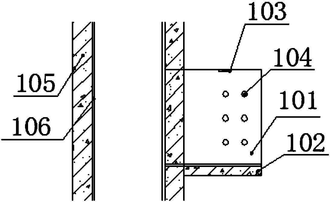
[0037] refer to Figure 1-10 , a prefabricated beam-column connection node, including a U-shaped corbel 1 and a prefabricated composite beam connection node 2, the U-shaped corbel 1 includes a U-shaped steel skeleton 101, precast concrete 102, fixing plate 103, and corbel studs 104, The U-shaped corbel 1 is connected to the structural column 105, and the structural column 105 is provided with a structural column steel frame 106, and one side of the structural column steel frame 106 is welded with a U-shaped steel frame 101, and the upper ends of the steel plates on both sides of the U-shaped steel frame 101 Both are welded with a fixed plate 103, the first bolt hole ...


PUM


Abstract

The invention relates to the technical field of beam-column connecting joints, in particular to a fabricated beam-column connecting joint. The fabricated beam-column connecting joint comprises a U-shaped bracket and a prefabricated laminated beam connecting joint, the periphery of a U-shaped steel skeleton is wrapped with prefabricated concrete; and the prefabricated laminated beam connecting joint comprises a connecting web plate, an upper flange plate and a lower flange plate and is connected with a structural beam, the upper flange plate and a fixing plate are connected and fixed by inserting bolts into second bolt holes and first bolt holes, and web plate studs and bracket studs are arranged in a staggered mode. According to the fabricated beam-column connecting joint, by combining with the steel structure industry with highly-developed industrialization and cooperating with a reinforced concrete combination technology, a system is innovated, the problems of inherent deficiencies of assembling of reinforced concrete connecting joints, environmental pollution of on-site construction, application of green building materials, high production cost, and supply side reform de-capacity are solved, and great significance is achieved.

Description

technical field [0001] The invention relates to the technical field of connecting nodes, in particular to an assembled beam-column connecting node. Background technique [0002] Prefabricated buildings have the advantages of improving project quality, shortening construction period, simplifying on-site construction process, reducing construction intensity, improving site environment, reducing pollution, and reducing wet work. At the same time, prefabricated buildings can effectively save resources and energy, improve material In terms of achieving building energy efficiency and structural performance, reducing the demand for site and environmental conditions for on-site construction, reducing the number of on-site construction labor, reducing construction waste and the adverse impact of construction on the environment, improving building function and structural performance, and effectively realizing the "four According to the green development requirements of saving energy and...

Claims


Application Information

Patent Timeline
Patent Type & Authority Applications(China)
IPC IPC(8): E04B1/21
CPCE04B1/215
Inventor 李金鹏
Owner BEIJING ZHIHUI YUNJIAN TECH CO LTD
Learn More