
Straddle method of cantilever of long-span simply supported steel truss beam of horizontal curve section

A technology of steel truss girder and curved section is applied in the field of cantilever erection of long-span simply supported steel truss girder in flat curve section, which can solve the problems of deviation of the span axis of cantilever bridges, achieve convenient construction, significant economic benefits, and reduce temporary construction of pier tops. Effects of facilities and site workload

Active Publication Date: 2014-04-02
CHINA MAJOR BRIDGE ENERGINEERING +1
View PDF7 Cites 11 Cited by
  • Summary
  • Abstract
  • Description
  • Claims
  • Application Information

AI Technical Summary

Problems solved by technology

[0007] The purpose of the present invention is to address the above-mentioned status quo, and aims to provide a cantilever bridge that can fundamentally solve the problem of the deviation of the span axis. Steel Truss Cantilever Method

Method used


Image

  • Straddle method of cantilever of long-span simply supported steel truss beam of horizontal curve section
  • Straddle method of cantilever of long-span simply supported steel truss beam of horizontal curve section
  • Straddle method of cantilever of long-span simply supported steel truss beam of horizontal curve section

Examples


Embodiment Construction

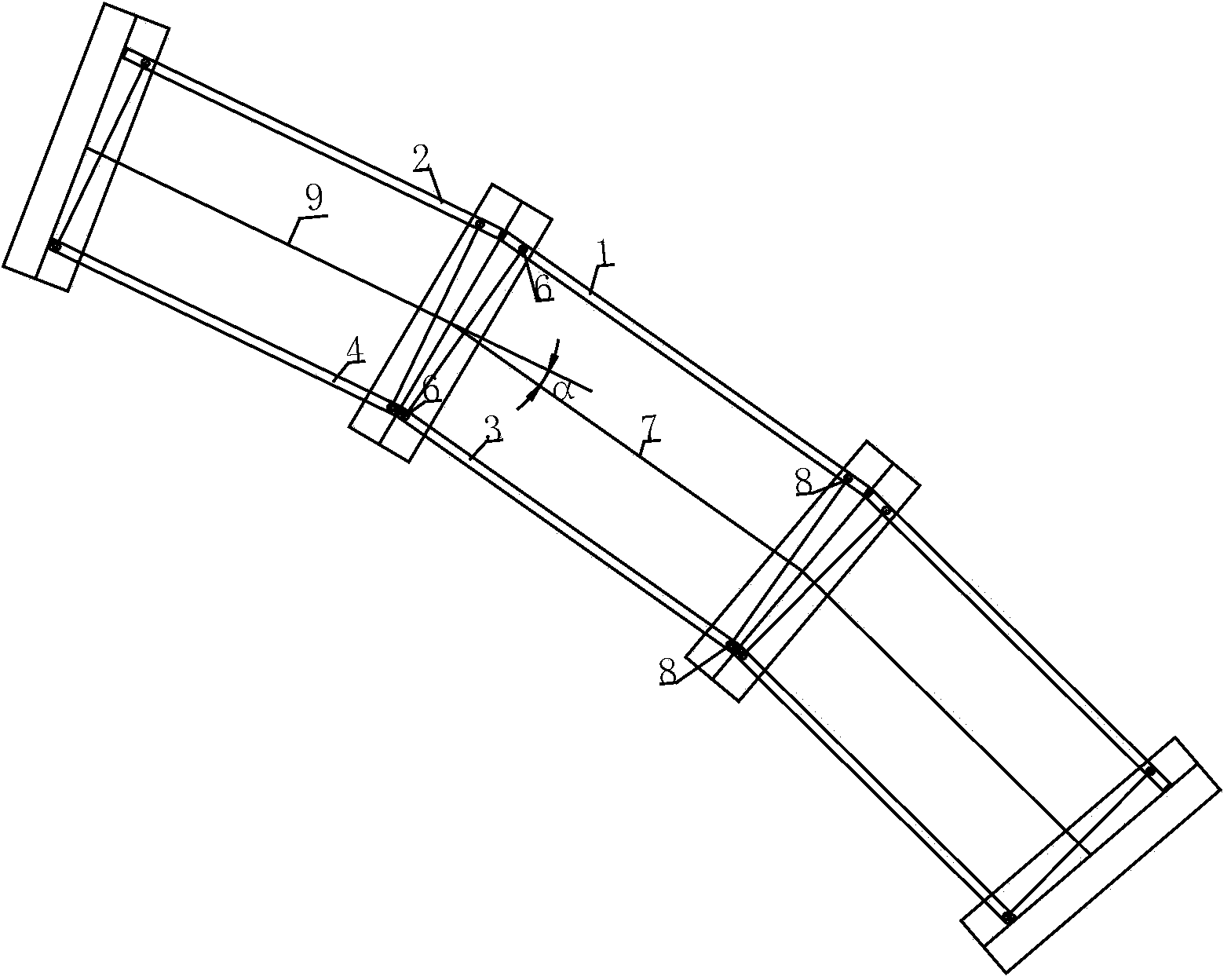
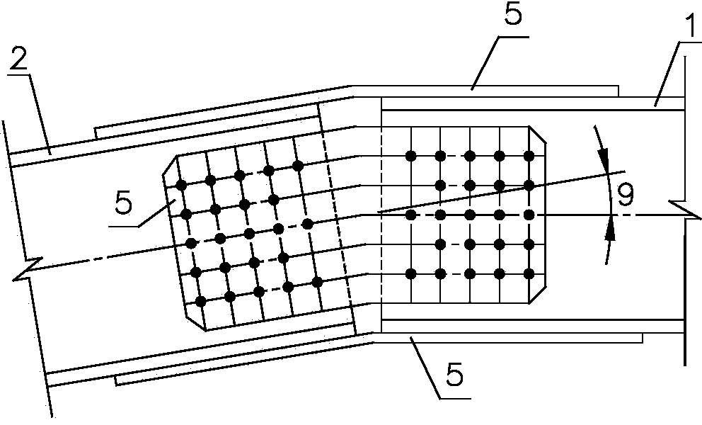
[0021] Refer to the attached figure 1 , 2 , 3, in conjunction with the specific steps of the cantilever erection method of simply supported steel truss girders in the horizontal curve section, the present invention is described in detail.

[0022] 1) Calculate the lengths of the inner and outer main truss members of the cantilever span curve and the inner and outer main truss members of the anchor span curve according to the radius of the horizontal curve, the position of the bridge span structure on the horizontal curve and the spacing of the main trusses.

[0023] The length of main truss members outside the curve = internode length + 1 / 2 x sinα x main truss spacing

[0024] The length of the main truss member inside the curve = internode length - 1 / 2 x sinα x main truss spacing

[0025] On the plane, the length of the outer main truss member of the cantilever span curve is greater than the length of the inner main truss member of the curve, and the difference is sinα×main...


PUM


Abstract

The invention relates to a straddle method of a cantilever of a long-span simply supported steel truss beam of the horizontal curve section. The straddle method comprises calculating the lengths of main truss rods arranged on the inner side and the outer side of a cantilever span curve and main truss rods arranged on the inner side and the outer side of an anchor span curve according to the radius of a horizontal curve, the position on the horizontal curve of a bridge span structure and the main truss spacing; hoisting the main truss rods arranged on the inner side and the outer side of the cantilever span curve to the position of a permanent support arranged at the top of an Nth pier, enabling the permanent support arranged at the pier top and the main truss rods arranged on the inner side and the outer side of the anchor span curve to be connected together through a temporary connection structure and performing cantilever construction of steel beam rods along the design axis; removing the temporary connection structure after the bridge span is straddled in place. According to the straddle method of the cantilever of the long-span simply supported steel truss beam of the horizontal curve section, the horizontal pushing in-place operation of the steel beam in the process of construction is avoided successfully, the construction process is simplified, the straddle construction of the cantilever of the long-span simply supported steel truss beam of the horizontal curve section can be greatly simplified, the stress is reliable, the construction is convenient, the operation is simple, temporary construction facilities and field workloads of the pier top are reduced, the construction progress greatly speeds up, the construction cost is saved, and the economic benefit is remarkable.

Description

technical field [0001] The invention relates to a cantilever erection method of a large-span simply supported steel truss girder in a flat curve section. Background technique [0002] At present, the length of highway and railway bridge construction projects is generally more than several kilometers, or even tens of kilometers. Due to the demand for beam section wiring, such long lines cannot all be on straight sections, so a large number of non-navigable bridges may be arranged. on the curve segment. In order to reduce the difficulty of design, manufacture and construction, the multi-span simply supported structure is generally designed as a straight line segment, and the bridge spans are arranged on the flat curve "replacing the bend". For long-span simply supported steel truss bridges, cantilever assembly is an economical and feasible method and is widely used in construction. However, when the steel truss bridge is arranged on a flat curve, there will be a deflection a...

Claims


Application Information

Patent Timeline
Patent Type & Authority Applications(China)
IPC IPC(8): E01D21/10
Inventor 高宗余徐伟肖海珠张燕飞彭振华侯健梅新咏徐力郑清刚龚俊张建强胡文军罗扣何东升张金涛苑仁安王恒刘厚军唐斌戴慧敏
Owner CHINA MAJOR BRIDGE ENERGINEERING
Learn More