Impeller production clamp for passenger car turbocharger

A turbocharger and passenger car technology, applied in clamping, manufacturing tools, supports, etc., can solve the problems of low pass rate of processing, difficulty in guaranteeing impeller parts, heavy inspection workload, etc., and achieve product quality The effect of stability, saving auxiliary time, and convenient operation

Pending Publication Date: 2018-07-13
JIANGSU LIANCHENG PRECISION ALLOY TECH CO LTD
View PDF0 Cites 0 Cited by
  • Summary
  • Abstract
  • Description
  • Claims
  • Application Information

AI Technical Summary

Problems solved by technology

In the processing at home and abroad, it is difficult to guarantee the shape and position tolerance of such parts
In the prior art, when machining the taper hole in the middle of the impeller close to the reference plane A, a fixture is usually used to clamp the impeller part from a certain position and then process the taper hole. This clamping method itself is very one-sided, making it very difficult It is difficult to ensure that the axis of the impeller parts does not shake during processing, so the pass rate of processing is not high, and because the high pass rate cannot be guaranteed, the follow-up inspection workload is very large, and the inspection methods are all carried out on three-coordinate machines, so it is time-consuming and laborious ; and, despite this, the cost of this fixture for clamping the parts is still very high, at hundreds of thousands of yuan, the production is difficult, the cycle is long, and it is not conducive to product changeover, so people urgently need to find a better clamping method

Method used


Image

  • Impeller production clamp for passenger car turbocharger
  • Impeller production clamp for passenger car turbocharger
  • Impeller production clamp for passenger car turbocharger

Examples


Embodiment Construction

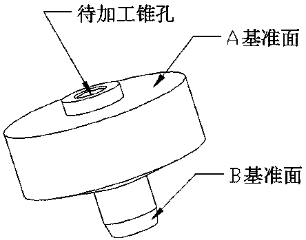
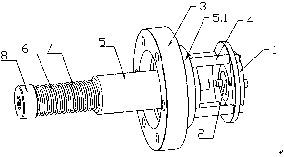
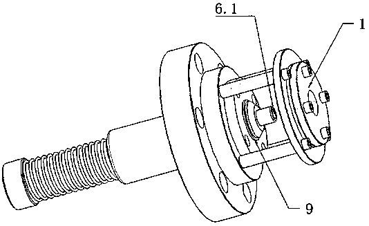
[0024] like Figure 2-4 As shown, the impeller production jig of a passenger car turbocharger includes a linear optical axis 6 and a linear bearing 5 sleeved on the front end of the linear optical axis 6. On the linear optical axis 6, the rear end of the linear bearing 5 is also A compression spring 7 and a retaining ring 8 are provided, and a boss 5.1 is provided on the front end of the linear bearing 5, and a flange 3 is sleeved outside the linear bearing 5 and clamped at the boss 5.1 , the boss 5.1 also supports an A reference plane positioning plate 1 at the front end of the linear optical axis 6 and perpendicular to the axial direction of the linear optical axis 6 through the bracket 4, and the A reference plane positioning plate 1 is provided with a through hole, A circle of steps matching the structure of the A reference plane of the part 2 is provided around the through hole, and a tapered positioning hole 6.1 is also provided at the front end of the linear optical axi...


PUM


Abstract

The invention discloses an impeller production clamp for a passenger car turbocharger. The impeller production clamp comprises a linear optical shaft and a linear bearing arranged at the front end ofthe linear optical shaft in a sleeving mode. A compression spring and a spring check ring are further arranged on the linear optical shaft and at the rear end of the linear bearing; a circle of boss is further arranged at the front end of the linear bearing; a flange plate is arranged outside the linear bearing in a sleeving mode and clamped to the boss; an A datum plane positioning plate locatedat the front end of the linear optical shaft and perpendicular to the axis direction of the linear optical shaft is further supported on the boss through supports; and a conical positioning hole is further formed in the front end of the linear optical shaft, and the conicity of the conical positioning hole is matched with the conicity of a B datum plane. The parallel deviation is controlled through a front positioning mode, and the bounce mode is controlled through the linear optical shaft with the rear conical hole; the clamp manufacturing cost is reduced, clamping precision is high, and machined products are stable in quality and good in consistency; and full inspection is not needed, the spot check period is prolonged, and the production period is greatly shortened.

Description

technical field [0001] The invention relates to a production jig for an impeller of a passenger car turbocharger. Background technique [0002] For the impeller, the key component in the passenger car turbocharger, this component has strict requirements in terms of material and machining accuracy. Its structure is as follows: figure 1 shown. The part marked in the figure is the surface to be machined (the machined surface is a taper hole), and the rest is the casting blank surface. There are two places for shape and position tolerance requirements on the machined surface and the non-machined surface, one is parallel difference, and the other is runout. They are all for the non-processed surface, which is very difficult to guarantee. Among the impeller parts, the non-processed surface is figure 1 The A datum plane and the B datum plane shown in , where the A datum plane is a vertical plane, and the B datum plane is a conical plane. In the processing at home and abroad, it ...

Claims


Application Information

Patent Timeline
Patent Type & Authority Applications(China)
IPC IPC(8): B23Q3/12
CPCB23Q3/12
Inventor 臧俊国李俊伟张昊潘开锋
Owner JIANGSU LIANCHENG PRECISION ALLOY TECH CO LTD
Why Eureka
Try Eureka