Chain cleaning device

A technology for cleaning devices and chains, which is applied in spraying devices, cleaning methods and tools, cleaning methods using liquids, etc., can solve the problems of large manpower consumption, uneven meshing, poor precision, etc., and achieve labor time saving and good work intensity , the effect of novel structure

Inactive Publication Date: 2018-07-13
CHENGDU PUJIANG KEXIAN TECH
View PDF0 Cites 0 Cited by
  • Summary
  • Abstract
  • Description
  • Claims
  • Application Information

AI Technical Summary

Problems solved by technology

[0002] The chain is generally a metal link or ring, and is mostly used for mechanical transmission. The chain can be divided into short-pitch precision roller chain, short-pitch precision roller chain, curved plate roller chain for heavy-duty transmission, and cement machinery chain. , Leaf chain, widely used in the field of mechanical equipment, is an important transmission part in mechanical transmission. In the process of manufacturing the chain, it is inevitable that there will be oil, cutting chips, dust and other impurities on the surface. If it is directly assembled and used, these impurities are very It is easy to cause uneven meshing, poor precision or deformation. The existing technology is generally manual spray cleaning. This method requires a lot of manpower, and the efficiency is low and the cleaning effect is poor. Therefore, it is very important to design a chain cleaning device. necessary

Method used


Image

  • Chain cleaning device
  • Chain cleaning device
  • Chain cleaning device

Examples


Embodiment Construction

[0017] The following will clearly and completely describe the technical solutions in the embodiments of the present invention with reference to the accompanying drawings in the embodiments of the present invention. Obviously, the described embodiments are only some, not all, embodiments of the present invention. Based on the embodiments of the present invention, all other embodiments obtained by persons of ordinary skill in the art without making creative efforts belong to the protection scope of the present invention.

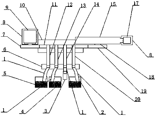
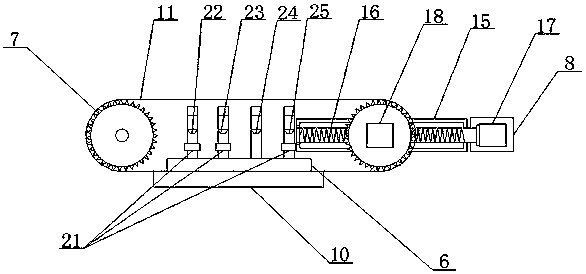
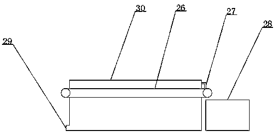
[0018] see Figure 1~4 , in an embodiment of the present invention, a chain cleaning device includes a connecting pipe 1, an oil storage tank 2, a blower 3, a water reservoir 4, a detergent storage tank 5, a fixing seat 6, a sprocket 7, and a protection tank 8. Servo motor one 9. Residue separation device 10, chain 11, cleaning agent pipe 12, water pipe 13, ventilation pipe 14, fixed plate 15, threaded rod 16, servo motor two 17, fixed block 18, sprocket two 1...


PUM


Abstract

The invention discloses a chain cleaning device. The chain cleaning device comprises a servo motor I, a chain wheel I and an oil spray nozzle. A chain wheel I is fixedly connected to an output shaft of the servo motor I through a key; a chain is arranged on the chain wheel I; the other end of the chain is connected onto a chain wheel II; a fixing block is hinged to the center of the chain wheel IIand is arranged in a sliding chute formed in a fixing plate; a through hole is formed in the center of the fixing block; a screw thread is formed in the through hole; the fixing block is matched witha threaded rod through the screw thread; one end of the threaded rod is in interference fit to a rolling bearing in a side wall of the fixing plate; the other end of the threaded rod penetrates through the side wall of the fixing plate and is fixedly connected onto an output shaft of a servo motor II through a key; a fixing base is arranged on one side, far away from the servo motor I, of the chain; a cleanser pipeline, a water through pipeline, a ventilation pipeline and an oil through pipeline are sequentially fixed onto the fixing base; and the bottom part of the cleanser pipeline is connected with a cleanser storage box through a connecting pipe.

Description

technical field [0001] The invention relates to the technical field of mechanical manufacturing, in particular to a chain cleaning device. Background technique [0002] The chain is generally a metal link or ring, and is mostly used for mechanical transmission. The chain can be divided into short-pitch precision roller chain, short-pitch precision roller chain, curved plate roller chain for heavy-duty transmission, and cement machinery chain. , Leaf chain, widely used in the field of mechanical equipment, is an important transmission part in mechanical transmission. In the process of manufacturing the chain, it is inevitable that there will be oil, cutting chips, dust and other impurities on the surface. If it is directly assembled and used, these impurities are very It is easy to cause uneven meshing, poor precision or deformation. The existing technology is generally manual spray cleaning. This method requires a lot of manpower, and the efficiency is low and the cleaning e...

Claims


Application Information

Patent Timeline
Patent Type & Authority Applications(China)
IPC IPC(8): B08B3/02B08B3/08B08B13/00F26B21/00B05B13/02
CPCB08B3/022B05B13/02B08B3/08B08B13/00F26B21/00
Inventor 陈清尧
Owner CHENGDU PUJIANG KEXIAN TECH
Why Eureka
Try Eureka