Eureka AIR delivers breakthrough ideas for toughest innovation challenges, trusted by R&D personnel around the world.

Light-transmitting intramedullary nail distal bolt sighting device

A technology of intramedullary nailing and distal locking, applied in the field of medical devices, can solve the problems of doctors, patients, physiological hazards, high surgical technical requirements, aiming failure, etc., and achieve the goals of reducing operation time, simplifying operation steps, and improving aiming accuracy Effect

Pending Publication Date: 2018-07-13
KANGHUI MEDICAL INNOVATION
View PDF0 Cites 10 Cited by
  • Summary
  • Abstract
  • Description
  • Claims
  • Application Information

AI Technical Summary

Problems solved by technology

The mechanical positioning and pressing bar technology is a common general technology in China at present, but the success rate of this aiming method is very low, and the problem of aiming failure often occurs; the magnetic navigation positioning and aiming technology, although its positioning is relatively accurate, but it is difficult to operate during the operation. The problem of response delay will also occur in the process, which will lead to the failure of aiming, and more importantly, its cost is too high; the success rate of unarmed aiming technology can reach 100%, but it requires higher surgical skills for doctors, and Long-term exposure to the X-ray environment will cause serious harm to the physiology of doctors and patients

Method used


Image

  • Light-transmitting intramedullary nail distal bolt sighting device
  • Light-transmitting intramedullary nail distal bolt sighting device
  • Light-transmitting intramedullary nail distal bolt sighting device

Examples


Embodiment Construction

[0030] Refer to attached Figure 1-7 , a light-transmissible intramedullary nail distal locking nail aiming device includes an intramedullary nail 1, a handle 2, a proximal connecting guide rod 3, a distal adjustment mechanism, and a distal aiming frame 7.

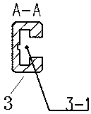
[0031] The handle 2 is a bent part. The intramedullary nail 1 and the handle 2 are metal parts, and the other proximal connecting guide rod 3, connecting guide rod 4, distal connecting guide rod 5 and distal aiming frame 7 are made of X-ray transparent material, such as carbon Other light-transmitting materials with high hardness such as cellulose fiber. One end of the handle 2 is fixedly connected with the intramedullary nail 1 by bolts. The handle 2 and the proximal connecting guide rod 3 are positioned through two pin holes, and then threaded through the connecting bolt 2 8 . The proximal connection guide rod 3 is provided with a chute (groove) 3-1, which is designed as figure 2 , 4 As shown, there are several bal...


PUM


Abstract

The invention relates to the field of medical apparatuses for orthopedic traumas, in particular to fracture intramedullary fixing, and a light-transmitting intramedullary nail distal bolt sighting device. The light-transmitting intramedullary nail distal bolt sighting device comprises a handle, a near-end connecting guide rod, a far-end adjusting mechanism and a far-end sighting shelf; one end ofthe handle is fixedly connected with an intramedullary nail through bolts, and the handle and the near-end connecting guide rod are located through two pin holes and a dowel, and are then in threadedconnection through a second connecting bolt; the far-end adjusting mechanism is assembled by a connecting guide rod and a far-end connecting guide rod, and a standard locating device and a guiding device are arranged at one end of the connecting guide rod; a locating hole of the far-end sighting shelf is formed in one end of the far-end connecting guide rod, a metal insert is fixedly inserted to the other end of the far-end connecting guide rod, and the far-end connecting guide rod and the connecting guide rod are combined and assembled through a dowel and a fixing bolt so that the far-end connecting guide rod and the connecting guide rod can rotate around the dowel. A transmission gear of which the modulus is matched with that of the screw is arranged at one end of the metal insert. The far-end sighting shelf and the far-end connecting guide rod are located through two pin holes and a dowel, and are then fixed through a first connecting bolt.

Description

technical field [0001] The invention relates to a medical instrument in the field of orthopedic trauma, in particular to a fracture intramedullary fixation device, in particular to a light-transmitting intramedullary nail distal locking nail aimer. Background technique [0002] At present, in the treatment of tubular bone fractures such as the femur and tibia, intramedullary nailing is often used. Under normal circumstances, when implanting a long intramedullary nail, due to the difference in the physiological curvature of the human medullary cavity and the existence of the isthmus of the medullary cavity, the intramedullary nail will be deformed unexpectedly inside the patient's medullary cavity, which will cause A distal pin aiming problem. When locking the distal locking nail, it is necessary to use a corresponding distal aiming device, which requires very high aiming accuracy. [0003] Currently commonly used aiming techniques include the following: mechanical position...

Claims


Application Information

Patent Timeline
IPC IPC(8): A61B17/72A61B17/90
CPCA61B17/725A61B2017/564A61B17/90
Inventor 陶凯潘辉
Owner KANGHUI MEDICAL INNOVATION
Why Eureka
Eureka Blog
Learn More