Camera module

A camera module and annular boss technology, which is used in image communication, instruments, televisions, etc., can solve the problems of unable to meet the requirements of module resolution, unable to meet the requirements of the module's optical axis, and high requirements for optical axis offset accuracy. Achieve the effect of improving image quality, preventing poor glue overflow, and stable and reliable structure

Pending Publication Date: 2018-07-10
NINGBO SUNNY OPOTECH CO LTD
View PDF8 Cites 3 Cited by
  • Summary
  • Abstract
  • Description
  • Claims
  • Application Information

AI Technical Summary

Problems solved by technology

[0002] At present, conventional FF modules are manufactured using the H / A process. This assembly method is mainly controlled by the shape of the mechanical parts and the alignment of the photosensitive area of ​​the chip. However, the accuracy of the manufacturing and testing will be affected by the shape tolerance of the mechanical parts, and the optical center cannot be truly controlled. The offset range, and the current high-pixel or dual-camera modules have high requirements for the accuracy of the optical axis offset, and the accuracy of the optical center offset needs to be controlled. Therefore, the current conventional design scheme cannot meet the requirements of the optical axis of the module, and cannot meet the resolution requirements of the module.

Method used


Image

  • Camera module
  • Camera module
  • Camera module

Examples


Embodiment Construction

[0037] In order to more clearly describe the embodiments of the present invention or the technical solutions in the prior art, the following will briefly introduce the drawings that are used in the embodiments. Apparently, the drawings in the following description are only some embodiments of the present invention, and those skilled in the art can also obtain other drawings according to these drawings without creative efforts.

[0038] When describing the embodiments of the present invention, the terms "vertical", "transverse", "upper", "lower", "front", "rear", "left", "right", "vertical", " The orientation or positional relationship expressed by "horizontal", "top", "bottom", "inner" and "outer" is based on the orientation or positional relationship shown in the relevant drawings, which are only for the convenience of describing the present invention and simplifying the description, and It is not to indicate or imply that the device or element referred to must have a particu...


PUM


Abstract

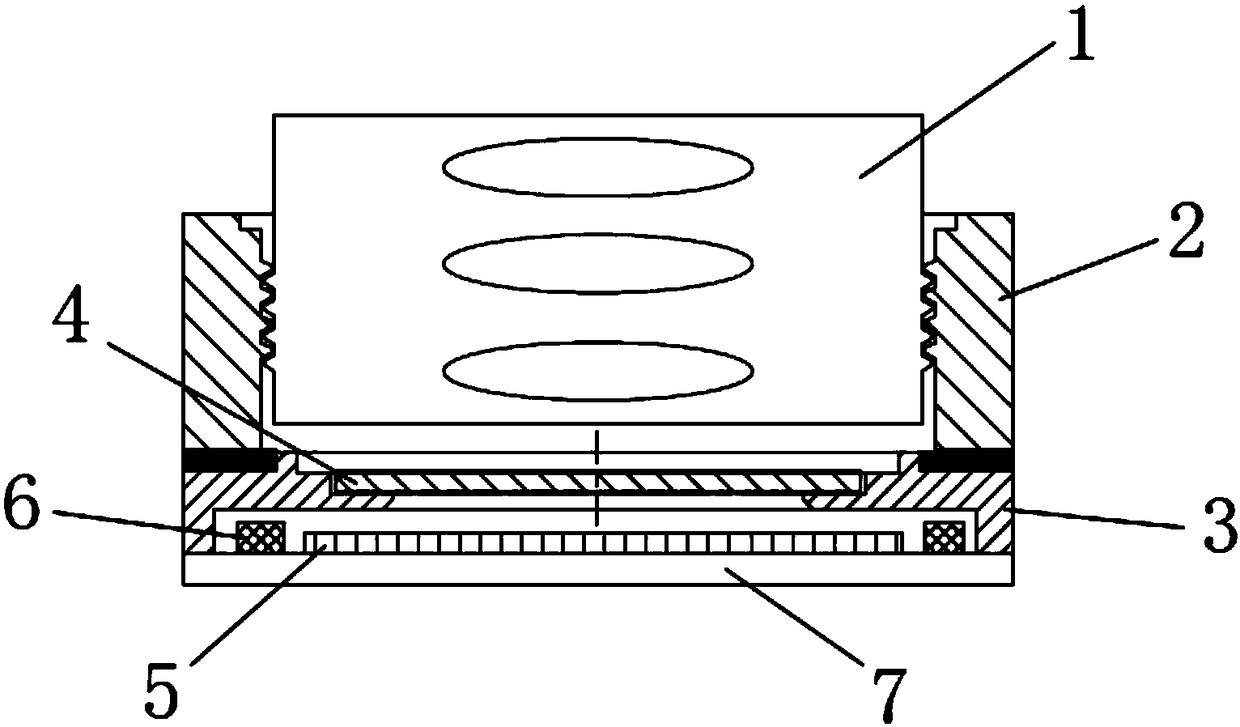
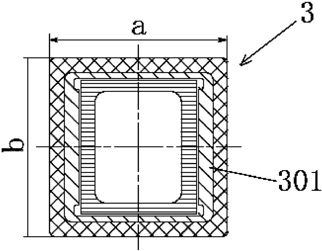
The invention relates to a camera module, which comprises an optical lens, a lens stand and a base, wherein the lens stand is used for bearing the optical lens; and the base is used for fixedly bearing the lens stand, the base has a length of 8 mm, a width of 8 mm and a height of 1 mm; and an annular boss is arranged on the base. The camera module has a reasonable structure, glue overflow can be prevented, the bonding strength is high, and the structure is stable and firm.

Description

technical field [0001] The invention relates to a camera module, in particular to a camera module capable of preventing glue overflow. Background technique [0002] At present, conventional FF modules are manufactured using the H / A process. This assembly method is mainly controlled by the shape of the mechanical parts and the alignment of the photosensitive area of ​​the chip. However, the accuracy of the manufacturing and testing will be affected by the shape tolerance of the mechanical parts, and the optical center cannot be truly controlled. The offset range, and the current high-pixel or dual-camera modules have high requirements for the accuracy of the optical axis offset, and the accuracy of the optical center offset needs to be controlled. Therefore, the current conventional design scheme cannot meet the requirements of the optical axis of the module, and cannot meet the resolution requirements of the module. . Contents of the invention [0003] The object of the p...

Claims


Application Information

Patent Timeline
Patent Type & Authority Applications(China)
IPC IPC(8): G02B7/02G02B7/00H04N5/225
CPCG02B7/006G02B7/02H04N23/55
Inventor 曾俊杰赵波杰方银丽胡国权
Owner NINGBO SUNNY OPOTECH CO LTD
Why Eureka
Try Eureka