Post-casting system for fabricated shear wall without template

A shear wall and prefabricated technology, which is applied in the direction of construction and building construction, can solve the problems of inability to directly install vertically and low assembly efficiency, and achieve the goal of avoiding overlapping and inability to install vertically, improving assembly efficiency, and ensuring safety Effect

Inactive Publication Date: 2018-07-10
CHANGDA BUILDING MATERIAL CO LTD
View PDF7 Cites 3 Cited by
  • Summary
  • Abstract
  • Description
  • Claims
  • Application Information

AI Technical Summary

Problems solved by technology

[0004] At present, during the cast-in-place process of the vertical joints of shear walls in the prior art, the stirrups of adjacent shear walls overlap and interfere with each other. Since the stirrups are rigid, they cannot be directly installed vertically, so the installation must Destroy the stirrups of the shear wall first, and then restore the stirrups to their original state, which increases the structural insecurity; at the same time, when pouring concrete in the prior art, a large number of steel bars need to be tied, and formwork needs to be set at the same time. After the pouring is completed, The formwork also needs to be removed, resulting in inefficient assembly

Method used


Image

  • Post-casting system for fabricated shear wall without template
  • Post-casting system for fabricated shear wall without template
  • Post-casting system for fabricated shear wall without template

Examples


Embodiment 1

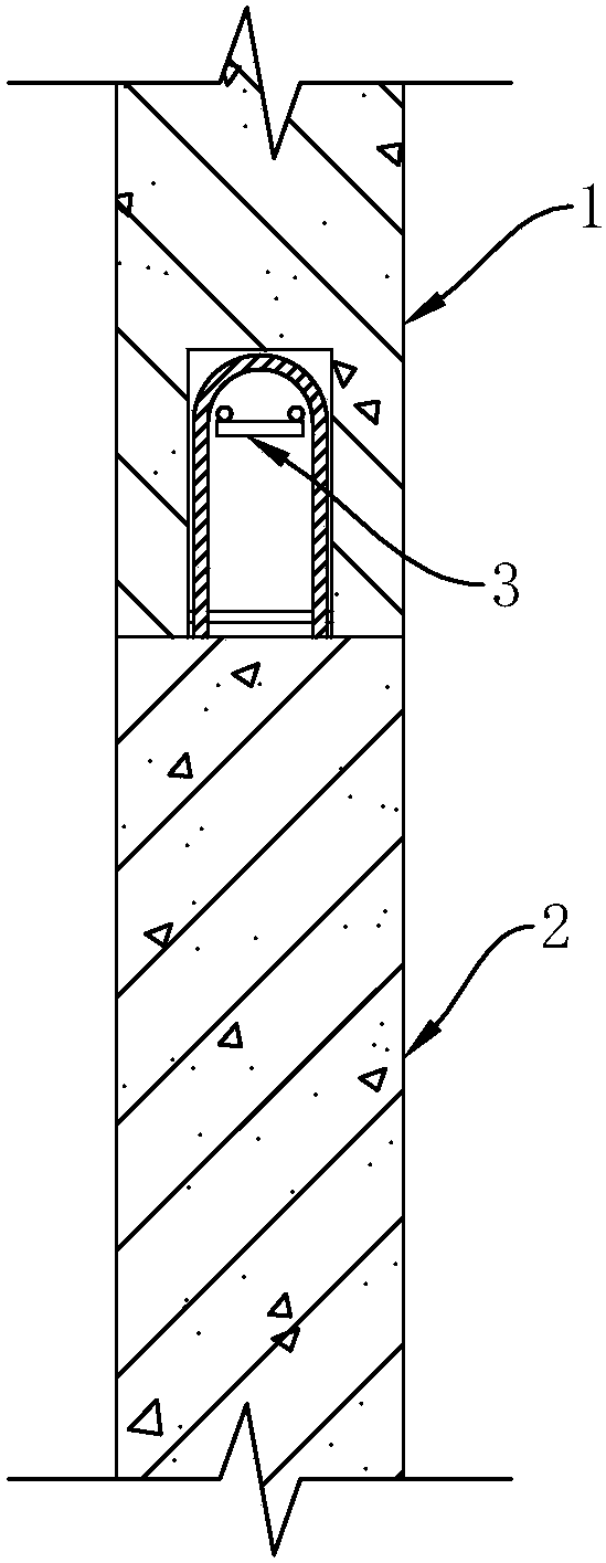
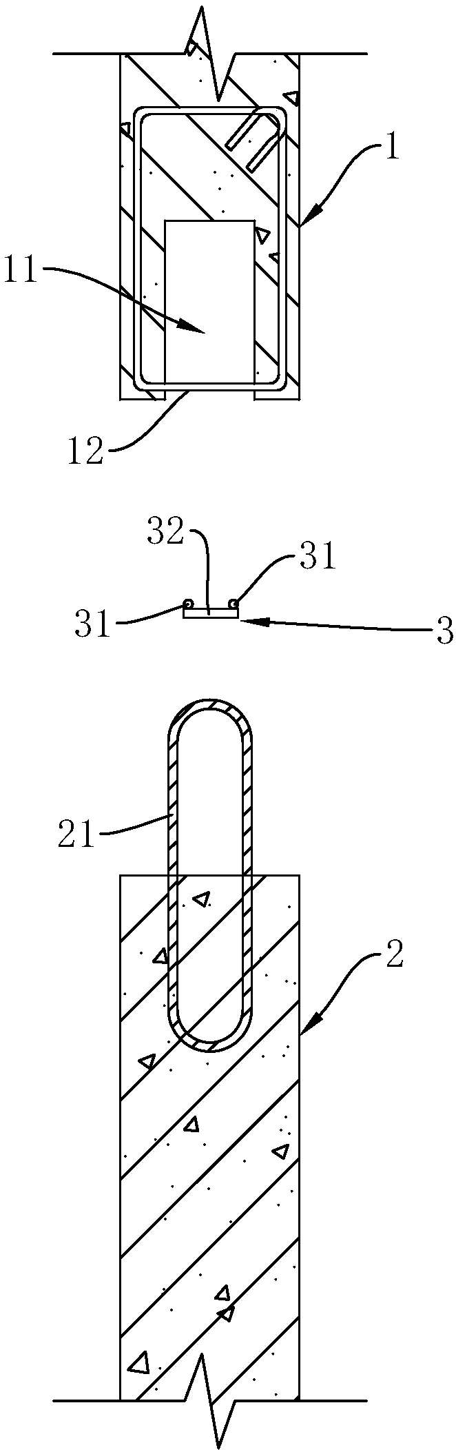
[0033] Such as figure 1 and figure 2 Commonly shown, a post-casting system for prefabricated shear walls without formwork, including a first shear wall 1 and a second shear wall 2, the end surface of the first shear wall 1 is provided with a vertical groove 11, so A plurality of stirrups 12 are arranged at vertical intervals in the vertical groove 11, preferably, the stirrups 12 are closed stirrups, and a plurality of insertion vertical grooves are arranged at vertical intervals on the second shear wall 2 The flexible connecting piece 21 inside the vertical groove 11 is poured with concrete, and the concrete connects the first shear wall 1 and the second shear wall 2 together.

[0034] The rear inserted reinforcement bar assembly 3 is arranged in the vertical groove 11 . In this way, before the concrete is poured in the vertical groove 11, the rear-inserted steel bar assembly 3 is directly inserted into the vertical groove 11, which saves the existing step of binding steel ...

Embodiment 2

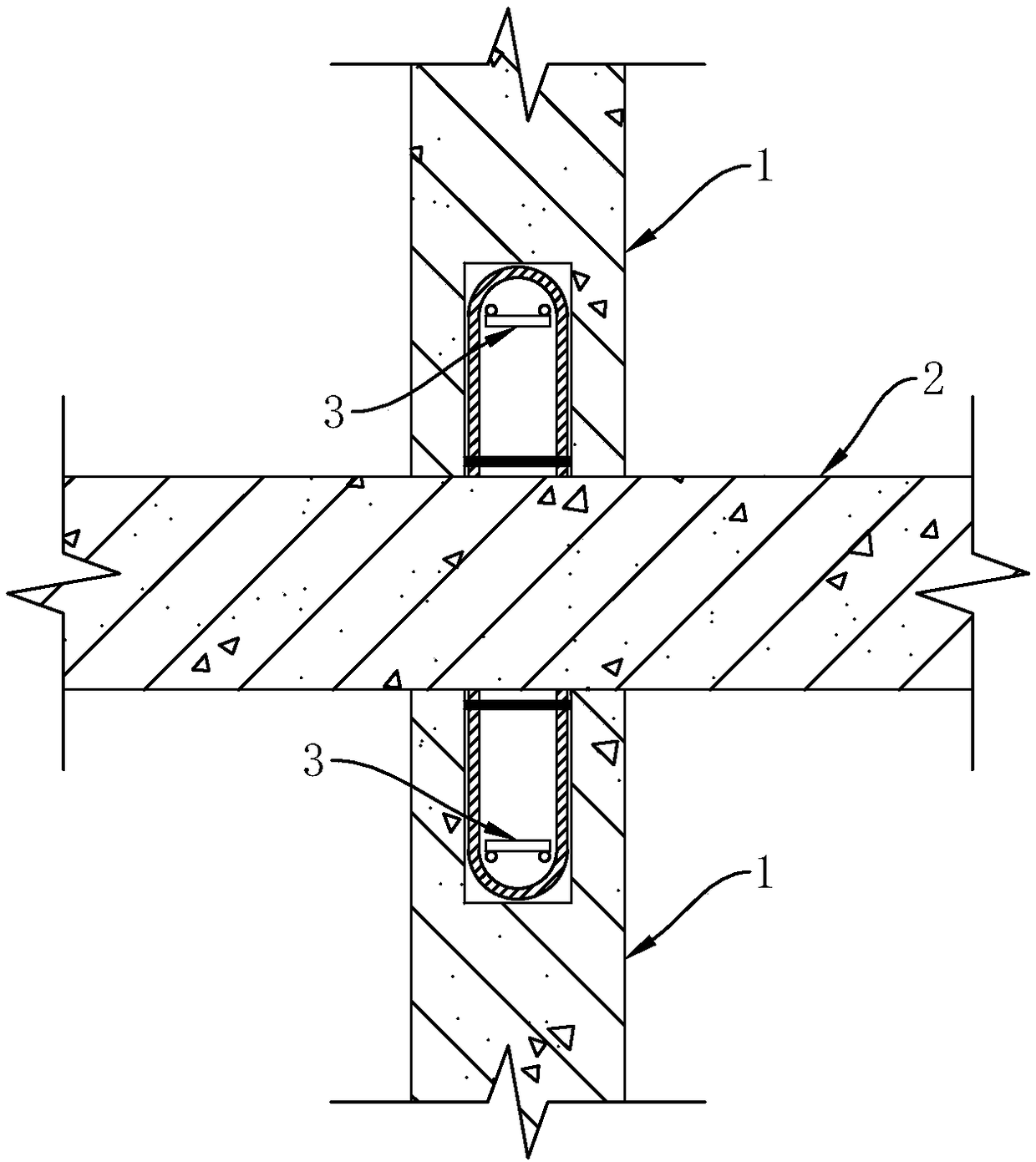
[0040] This embodiment is basically the same as Embodiment 1, the difference is that, as image 3 and Figure 4 Commonly shown, there are two rows of flexible connectors 21, and the two rows of flexible connectors 21 are symmetrically arranged on both sides of the second shear wall 2. Correspondingly, there are two first shear walls 1 and two first shear walls. The wall 1 is arranged symmetrically on both sides of the second shear wall 2, and the concrete connects the two first shear walls 1 and the second shear wall 2 to form a cross-shaped node.

[0041] In this embodiment, the middle part of each flexible connecting piece 21 is arranged in the second shear wall 2 , and its two ends extend out of the second shear wall 2 respectively.

Embodiment 3

[0043] This embodiment is basically the same as Embodiment 1, the difference is that, as Figure 5 and Figure 6 As shown together, the flexible connector 21 is arranged on one side of the second shear wall 2 and is arranged close to the end face of the second shear wall 2, and the concrete connects the first shear wall 1 and the second shear wall 2 to form a L-shaped nodes.


PUM


Abstract

The invention discloses a post-casting system for a fabricated shear wall without a template, and belongs to the technical field of connection of prefabricated building prefabricated components. The post-casting system comprises a first shear wall and a second shear wall, a vertical groove is formed in the end face of the first shear wall, and a plurality of stirrups are disposed in the vertical groove in the vertical direction at intervals; the second shear wall is provided with a plurality of flexible connectors inserted into the vertical groove, and the flexible connectors are arranged in the vertical direction at intervals; and concrete is poured into the vertical groove, and the concrete enables the first shear wall to be connected with the second shear wall. The post-casting system effectively avoids the current situation that the stirrups of edge members of the shear walls overlap each other and cannot be vertically installed, cast-in-place of vertical joints of the shear wallsis facilitated, and the safety of a structure is ensured; and at the same time, the process of supporting the template is omitted, and the assembly efficiency is improved.

Description

technical field [0001] The invention belongs to the technical field of connection of prefabricated building components, and in particular relates to a formwork-free post-casting system for a prefabricated shear wall. Background technique [0002] Prefabricated buildings refer to buildings in which some or all of the components of the building are prefabricated in the factory, then transported to the construction site, and the components are assembled through reliable connection methods. Specifically, after assembly at the construction site, usually between wall panels The vertical connection joints are cast-in-place, the main vertical stress-bearing steel grout anchor connection between the upper and lower wall panels, and the floor beams and slabs are superimposed and cast-in-site to form a whole. The advantage of this kind of building is that it can be constructed quickly, is less restricted by climate conditions, saves labor, and can improve the quality of construction. ...

Claims


Application Information

Patent Timeline
Patent Type & Authority Applications(China)
IPC IPC(8): E04B1/61
CPCE04B1/6125
Inventor 李飞周克家宁娜娜张恒铭赵海成李希文林萌高云峰王树军魏新新
Owner CHANGDA BUILDING MATERIAL CO LTD
Why Eureka
Try Eureka