
Post-grouting precast hollow pipe root pile structure and construction method

A technology of hollow tubes and tree root piles, which is applied in the direction of foundation structure engineering, sheet pile walls, buildings, etc., can solve the problems of complex construction and long construction period, and achieve the effect of protecting integrity and maintaining verticality

Active Publication Date: 2018-07-10
刘寅平
View PDF16 Cites 5 Cited by
  • Summary
  • Abstract
  • Description
  • Claims
  • Application Information

AI Technical Summary

Problems solved by technology

[0007] Aiming at the problems of low bearing capacity of prefabricated hollow pipe piles, insufficient loose soil strength at the bottom of piles at the side of piles, and problems such as the complicated process and long construction period of cast-in-place concrete tree root piles and post-grouting grouting construction methods, the present invention provides a post-injection Grout prefabricated hollow pipe tree root pile structure and construction method, its purpose is to improve the bearing capacity of prefabricated hollow pipe piles, reduce the settlement of pile foundation, improve the strength of soil layer around pile foundation, overcome the long construction period of grouting technology after grouting, the construction Complicated and other shortcomings, optimize the construction method and construction structure

Method used


Image

  • Post-grouting precast hollow pipe root pile structure and construction method
  • Post-grouting precast hollow pipe root pile structure and construction method
  • Post-grouting precast hollow pipe root pile structure and construction method

Examples


Embodiment Construction

[0036] The specific technical solutions of the present invention will be described in detail below with reference to the accompanying drawings.

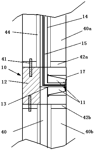
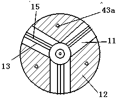
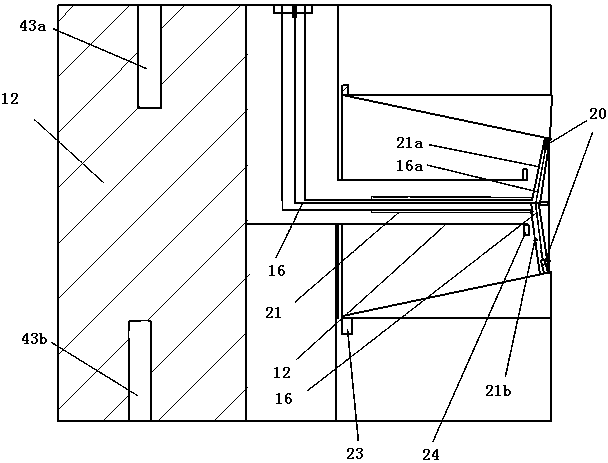
[0037] A post-grouting prefabricated tubular stump structure, figure 1 It is a schematic diagram of the longitudinal section of the prefabricated hollow tubular body along the left and right direction. figure 2 is a schematic diagram of the cross-sectional structure of the upper part of the connector 10 . The post-grouting prefabricated pipe stump structure includes a prefabricated hollow pipe and a connecting pin 41 at the butt joint of the prefabricated hollow pipe. A grout pouring pipe 14 is arranged inside the prefabricated hollow pipe, and a conduit 15 is arranged therebetween. The electric wire 16 runs through the conduit 15. The prefabricated hollow pipe The pipe butt joint part is provided with a connector 10, and the middle of the connector 10 is provided with a grout pouring pipe 14, a conduit, an electric wire and an u...


PUM


Abstract

The invention discloses a post-grouting precast hollow pipe root pile structure and a construction method, and belongs to the field of buildings. The precast hollow pipe is internally provided with acement slurry cast pipe and an electric wire. A connecting part is arranged on the butt-joint part of the precast hollow pipe and is a cylinder. A plurality of radial sliding parts are evenly arrangedon the parts, on the periphery of the cement slurry cast pipe, in the cylinder. A hollow radial sliding shaft is slidably arranged on the sides, close to the cement slurry cast pipe, of the radial sliding parts. A guide pipe and the electric wire are arranged in the radial sliding shaft, and a micro welding gun is arranged at the wire end and connected to a plurality of parts of the radial sliding parts. The radial sliding shaft communicates with the cement slurry cast pipe. The upper end, in the precast hollow pipe, of the electric wire is connected with an electric welding machine. Throughthe post-grouting precast hollow pipe root pile structure provided by the structure, the bearing capacity of the precast hollow pipe pile can be improved, settlement of a pile foundation is reduced, the strength of soil layers around the pile foundation is improved, and the defects that the post-grouting technology is long in construction period, complex in process and the like are overcome.

Description

technical field [0001] The invention relates to a pipe tree root pile structure and a construction method, in particular to a post-grouting prefabricated hollow pipe tree root pile structure and a construction method, belonging to the construction field. Background technique [0002] With the continuous development of the real estate industry, the height of buildings is also getting higher and higher. The foundation is the key to the high-rise buildings. When building the foundation, foundation piles are often pressed into the foundation or holes are drilled in the ground, and then concrete is poured to form the foundation of the building. The foundation piles pressed into the foundation are generally prefabricated hollow tubes, and the end faces of the piles are provided with flanges, flanges, etc. There are multiple connecting holes on the surface, and the prefabricated hollow pipes are connected vertically by the connecting pins inserted into the connecting holes. Figure...

Claims


Application Information

Patent Timeline
Patent Type & Authority Applications(China)
IPC IPC(8): E02D5/48E02D5/52E02D5/50E02D15/04
CPCE02D5/48E02D5/526E02D15/04E02D2250/003E02D2600/20Y02P60/40
Inventor 刘寅平李军华
Owner 刘寅平
Learn More