Network device test method, apparatus and system
A technology of network equipment and testing method, applied in the field of testing, can solve problems such as low testing efficiency of network testing equipment, and achieve the effect of solving low testing efficiency and improving testing efficiency
- Summary
- Abstract
- Description
- Claims
- Application Information
AI Technical Summary
Problems solved by technology
Method used
Image

Examples
Embodiment 1
[0029] An embodiment of the present invention provides a test system for network equipment.
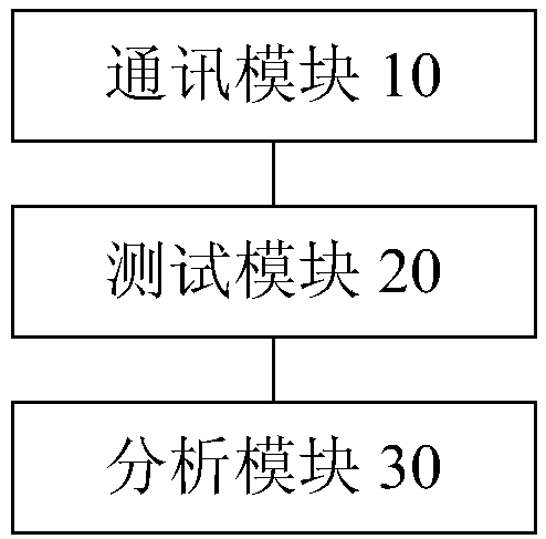
[0030] figure 1 is a schematic diagram of a test system for network equipment according to an embodiment of the present invention. Such as figure 1 As shown, the system includes: a communication module 10 , a testing module 20 and an analysis module 30 .
[0031] The communication module 10 is configured to obtain target messages obtained by simulating messages from substations based on target protocols in the network environment of the substation.
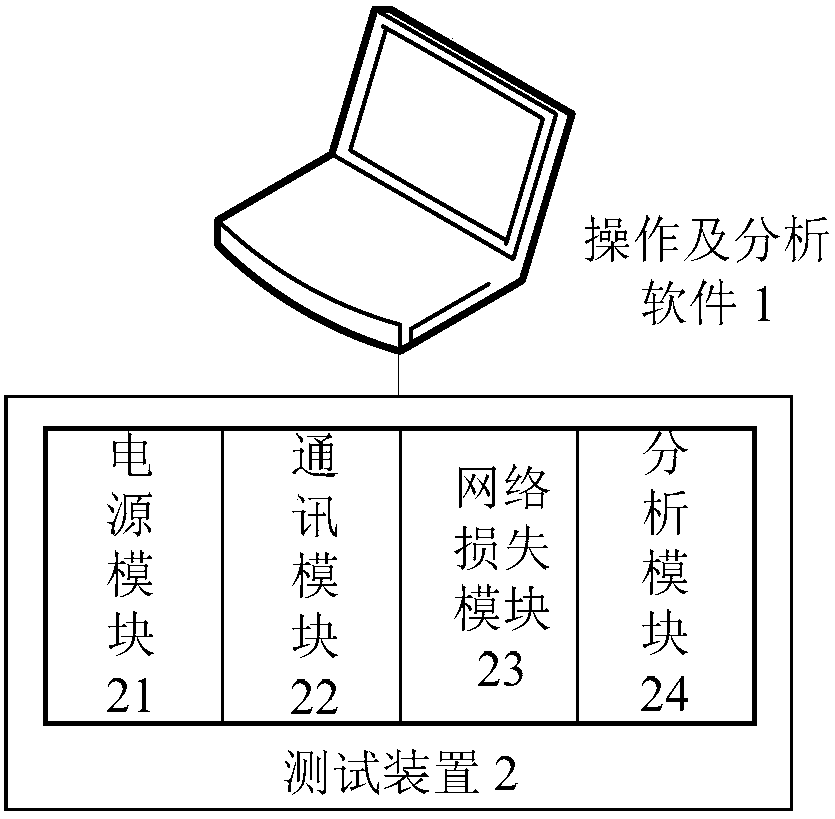
[0032] The network device testing system of this embodiment, that is, the network performance testing system, may include a testing device and host computer software. In order to meet the needs of optical fiber network testing in smart substations, the test device includes 2 pairs of 100M multimode optical fiber Ethernet interfaces and 4 100 / 1000M self-adaptive grid ports. The upper computer software can realize the control of the tes...
Embodiment 2
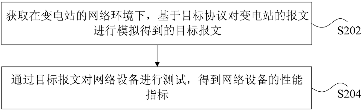
[0044] figure 2 It is a flow chart of a testing method for a network device according to an embodiment of the present invention. It should be noted that the method for testing a network device in this embodiment may be executed by the system for testing a network device in an embodiment of the present invention. Such as figure 2 As shown, the method includes the following steps:
[0045] Step S202, obtaining target messages obtained by simulating messages from substations based on the target protocol in the network environment of the substation.
[0046] In the technical solution provided in the above step S202 of the present application, the target message obtained by simulating the message of the substation based on the target protocol in the network environment of the substation is obtained. The substation may be a smart substation, and the target protocol may be the IEC61850 protocol. The target message is also the test message. The target protocol of this embodiment...
Embodiment 3
[0073] The technical solutions of the present invention will be illustrated below in conjunction with preferred embodiments.
[0074] This embodiment can be applied in a smart substation, and the importance of the switch as a node for gathering and forwarding information of the process layer and the station control layer is self-evident. The switch at the process layer transmits important sampling information SV and switch status, the status of primary equipment and the control signal GOOSE, and the switch at the station control layer is an important link in the communication between the substation and the control center. The performance of the switch directly affects the function of the secondary system of the substation. Due to various factors such as production quality, operating years, and operating environment, switches often have problems such as increased communication delay, increased packet loss rate, and abnormal network connection. The above-mentioned performance t...
PUM
 Abstract
Description
Claims
Application Information
 - R&D Engineer
- R&D Manager
- IP Professional
- Industry Leading Data Capabilities
- Powerful AI technology
- Patent DNA Extraction
Browse by: Latest US Patents, China's latest patents, Technical Efficacy Thesaurus, Application Domain, Technology Topic.
© 2024 PatSnap. All rights reserved.Legal|Privacy policy|Modern Slavery Act Transparency Statement|Sitemap