
Power electronic transformer-based alternating current/direct current microgrid coordinated control method

A technology of power electronics and coordinated control, which is applied in the field of transformers, can solve the problems of micro-grid distributed energy output and load fluctuations, frequent changes in operating status, and inability to transmit power to each other, so as to reduce the number of power feedbacks and the amount of control Effect of reducing information and relieving communication pressure

Active Publication Date: 2018-07-06
NANJING INST OF TECH
View PDF6 Cites 4 Cited by
  • Summary
  • Abstract
  • Description
  • Claims
  • Application Information

AI Technical Summary

Problems solved by technology

[0005] The existing definition of the operating state of the microgrid only starts from the perspective of distributed energy output and load, and fails to consider the impact of energy storage on the state of the microgrid. Therefore, the state of the microgrid is greatly affected by the output of distributed energy and load fluctuations. frequent changes
In the power control of the existing power electronic transformer to the AC and DC microgrid, the power between the AC microgrid and the DC microgrid cannot be transmitted to each other, and the control amount is complex and the target is not clear

Method used


Image

  • Power electronic transformer-based alternating current/direct current microgrid coordinated control method
  • Power electronic transformer-based alternating current/direct current microgrid coordinated control method
  • Power electronic transformer-based alternating current/direct current microgrid coordinated control method

Examples


Embodiment Construction

[0033] In order to make the object, technical solution and advantages of the present invention clearer, the present invention will be further described in detail below in conjunction with the accompanying drawings and embodiments. It should be understood that the specific embodiments described here are only used to explain the present invention, not to limit the present invention.

[0034] Unless the context clearly states otherwise, the number of elements and components in the present invention can exist in a single form or in multiple forms, and the present invention is not limited thereto. Although the steps in the present invention are arranged with labels, they are not used to limit the order of the steps. Unless the order of the steps is clearly stated or the execution of a certain step requires other steps as a basis, the relative order of the steps can be adjusted. It can be understood that the term "and / or" used herein refers to and covers any and all possible combina...


PUM


Abstract

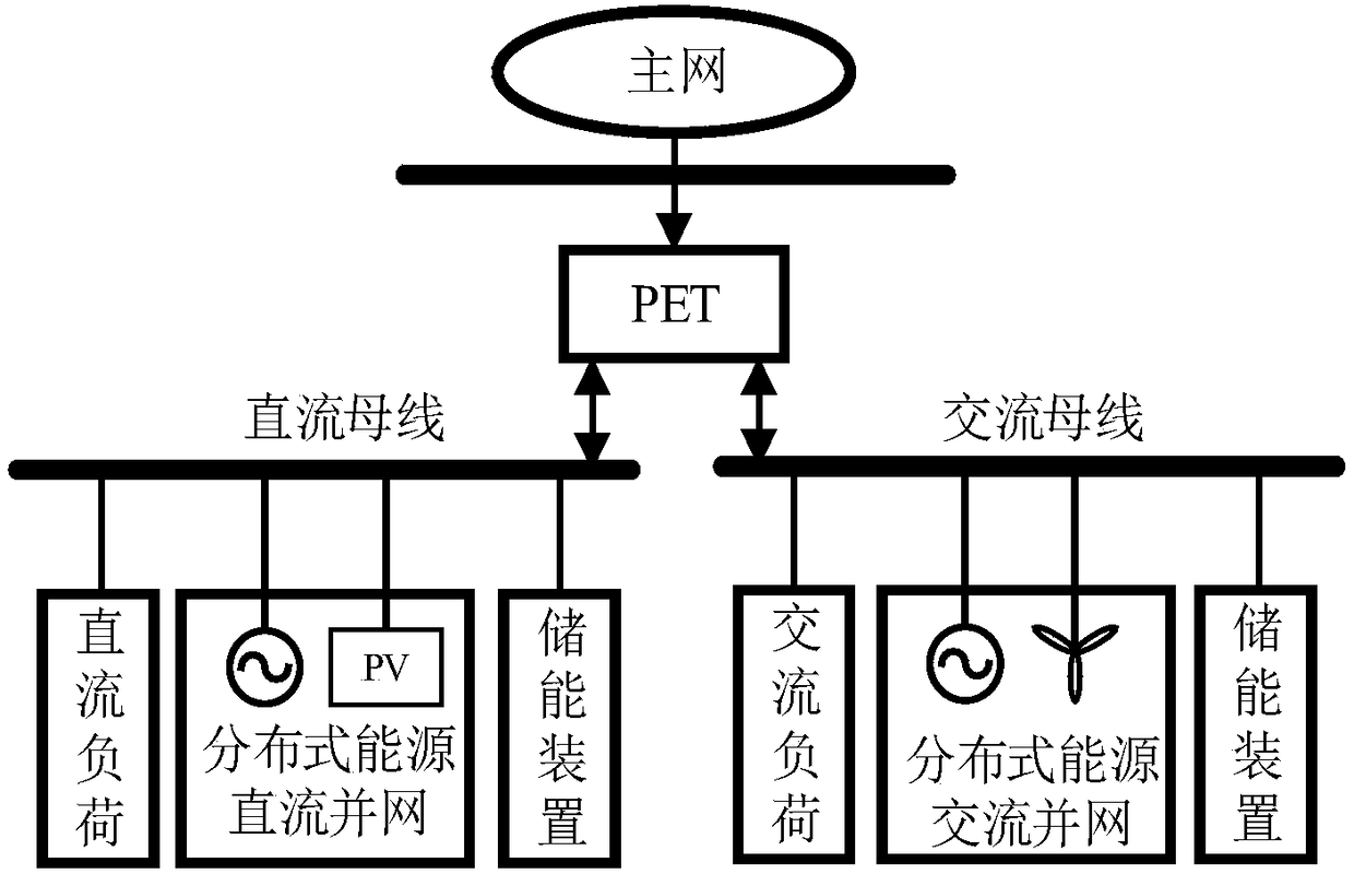
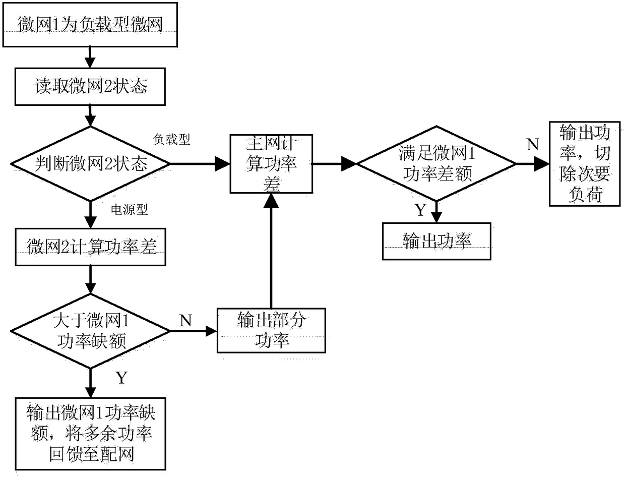
The invention provides a power electronic transformer-based alternating current / direct current microgrid coordinated control method. The power electronic transformer-based alternating current / direct current microgrid coordinated control method includes the following steps that: 1, the real-time operation data of a microgrid are collected, and the predicted power curves of the distributed energy and load of the microgrid are established; 2, a distributed energy output power average value and a load demand power average value during a current scheduling period are calculated, so that the energystorage state-of-charge expected value of the microgrid can be obtained; 3, the operation state types of the microgrid are divided; and 4, a power electronic transformer controls the flow direction and magnitude of the power of the alternating current / direct current microgrid according to the operation state types of the microgrid. With the power electronic transformer-based alternating current / direct current microgrid coordinated control method adopted, the maximum consumption of distributed energy can be realized, the service life of an energy storage battery can be improved, and the numberof the times of the power feedback of the microgrid to a distribution network and power loss generated during the power feedback can be decreased.

Description

technical field [0001] The invention belongs to the technical field of transformers, in particular to an AC / DC microgrid coordination control method based on power electronic transformers. Background technique [0002] The utilization of large-scale distributed energy resources (Distributed Energy Resources, DER) is of great significance to the protection of the environment, adjustment of energy structure and power consumption in remote areas. DER is affected by time and space factors and the power fluctuates greatly. Energy storage technology is an effective smoothing measure for this intermittent fluctuation. The microgrid composed of sources, loads, and storages is a strong support for the stable operation of the power grid. [0003] The existing micro-grid is mainly based on AC. With the rapid development and wide application of DC power sources and loads such as photovoltaics, energy storage, and electric vehicles, the DC power distribution form used in data center pow...

Claims


Application Information

Patent Timeline
IPC IPC(8): H02J3/02H02J3/32
CPCH02J3/02H02J3/32
Inventor 郝思鹏周宇黄琳黄堃刘思亦杨李星
Owner NANJING INST OF TECH
Learn More