
Phase plate capable of producing light orbital angular momentum superposition

A technology of orbital angular momentum and phase plate, which is applied in the field of phase plate, can solve the problems of complex structure design, large volume, and inability to be used in the manufacture of micro-nano chip integrated devices, and achieve the effect of easy integration and simple structure

Active Publication Date: 2018-07-06
GUILIN UNIV OF ELECTRONIC TECH
View PDF5 Cites 9 Cited by
  • Summary
  • Abstract
  • Description
  • Claims
  • Application Information

AI Technical Summary

Problems solved by technology

Currently, OAM beams generally use spiral phase plates (S.Oemrawsingh, et al., Appl. Optics, 2004, 43, 688–694.), Q-plates (L.Marrucci, et al., Phys.Rev.Lett., 2006, 96(16):163905.), holograms produced by spatial light modulators (G.Gibson, et al.Opt.express, 2004, 12(22), 5448-5456), specially designed metasurfaces (Fuyong Yue, et al.Adv.Mater., 2017, 29, 1603838) and integrated angular momentum gratings (Q.Xiao, etal.Opt.Express, 2016, 24(4), 3168-3176), etc., but these devices are have their own limitations
For example: spiral phase plates and Q-plates generally can only generate light carrying a single OAM mode; although spatial light modulators can generate light in OAM superposition states, they are too bulky to be used to manufacture integrated micro-nano chips. Integrated devices; while metasurfaces and integrated angular momentum gratings generally can only generate light in a small number of superposition states of OAM modes. As the number of OAM modes increases, their structural design will become extremely complex
It can be seen that among the devices used to generate OAM beams, there is still a lack of devices that can simultaneously satisfy the conditions of simple structure, easy integration, and the ability to generate a large number of OAM mode superpositions.

Method used


Image

  • Phase plate capable of producing light orbital angular momentum superposition
  • Phase plate capable of producing light orbital angular momentum superposition
  • Phase plate capable of producing light orbital angular momentum superposition

Examples


Embodiment Construction

[0009] The following will clearly and completely describe the technical solutions in the embodiments of the present invention with reference to the accompanying drawings in the embodiments of the present invention. Obviously, the described embodiments are only some, not all, embodiments of the present invention. Based on the embodiments of the present invention, all other embodiments obtained by persons of ordinary skill in the art without making creative efforts belong to the protection scope of the present invention.

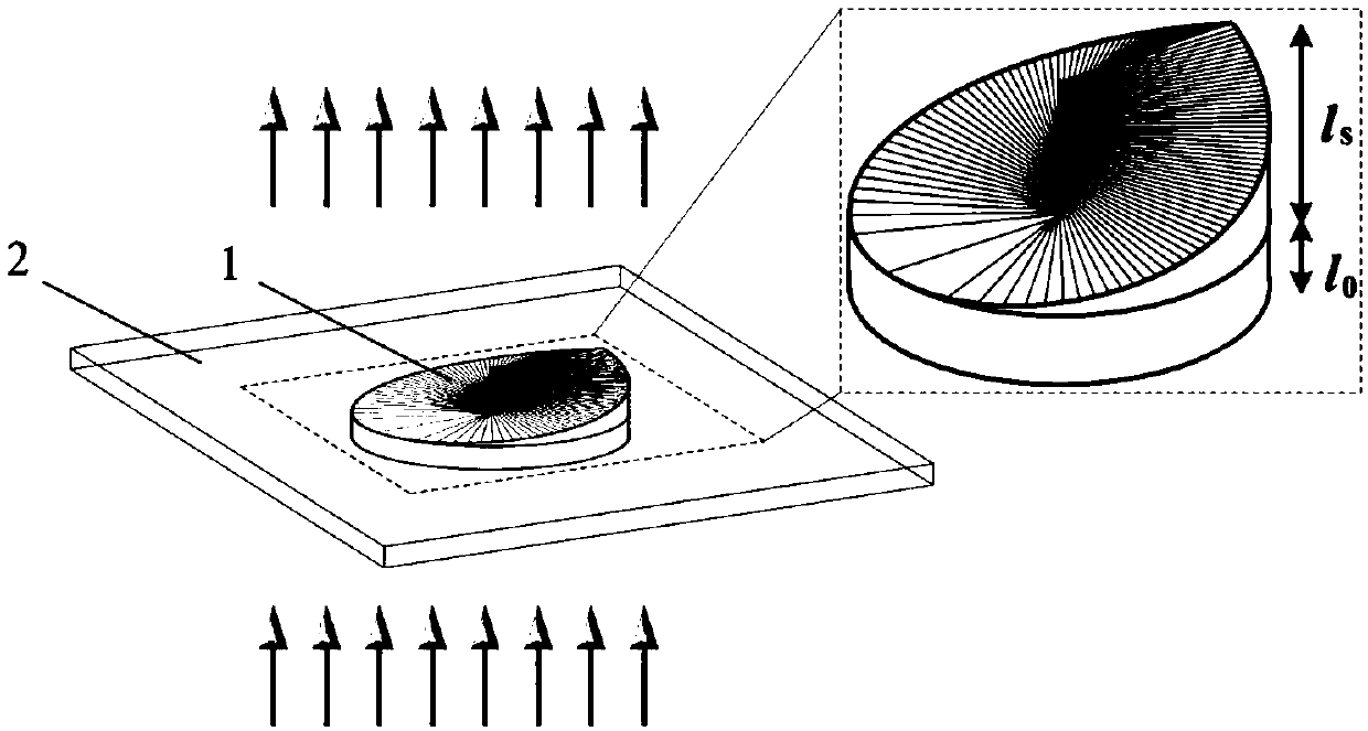
[0010] The schematic diagram of the phase plate (hereinafter referred to as the phase plate) that can produce the superposition state of optical orbital angular momentum disclosed by the present invention can be found in figure 1 , the phase plate includes a core phase modulation structure (1) and packaging material (2). The thickness of the core phase modulation structure satisfy in is the base thickness, is the step thickness, is the azimuth, and α...


PUM


Abstract

The invention discloses a phase plate capable of producing light orbital angular momentum superposition. The phase plate capable of producing light orbital angular momentum superposition comprises a core phase modulating structure (1) and encapsulating materials (2); the thickness l of the core phase modulating structure changes along with the azimuth angle phi and meets A, wherein l0 is the thickness of a base, ls is phase step thickness, and alpha is a variable angle; the core phase modulating structure can modulate the phase of a light field; the encapsulating materials are mounted outsidethe core phase modulating structure for protecting the core phase modulating structure. When the phase plate capable of producing light orbital angular momentum superposition is in work, laser carrying single orbital angular momentum is perpendicularly incident into the phase plate and then passes through the core phase modulating structure, and accordingly the phase of the laser is modulated andthe laser is converted into light carrying superposed orbital angular momentums.

Description

technical field [0001] The invention relates to a technology for generating a superposition state of light orbital angular momentum, in particular to a phase plate capable of generating a superposition state of light orbital angular momentum. Background technique [0002] In 1992, it was discovered that photons can carry orbital angular momentum (OAM) in addition to spin angular momentum (SAM). The orbital angular momentum of light corresponds to the helical phase wavefront of light, which passes through to describe, where is the azimuth angle, is a topological charge, and different topological charge values ​​represent different OAM eigenmodes. After nearly 30 years of development, optical OAM has been widely used in many fields because of its unique properties. For example: in optical communication, OAM has an infinite number of mutually orthogonal eigenmodes and is used in OAM multiplexing technology, which greatly increases the communication capacity; in quantum i...

Claims


Application Information

Patent Timeline
IPC IPC(8): G02F1/00G02F1/01
CPCG02F1/0009G02F1/0054G02F1/0102
Inventor 刘厚权苑立波滕传新
Owner GUILIN UNIV OF ELECTRONIC TECH
Learn More