


Quick Research
Generate reliable direction feasibility study reports for your R&D in just a few steps.

Technical Q&A
Discover and master advanced knowledge NOW. Basics, ideas, possibilities, all at once.

Find Solutions
As an expert in R&D theories, this can generate solutions to your technical problems instantly.

Evaluate Feasibility
Analyze your overall solution with one click, know your potential R&D risks in advance.

Monitor Landscape
Get weekly tech updates, stay abreast of the latest tech innovations and key insights.
A single photon detector system and control method
A single-photon detector and controller technology, which is applied in the field of quantum physics engineering applications, can solve problems such as unsuitable for application development, easy to generate errors, and complicated operations, so as to shorten the detection dead time, increase the output code rate, and not reduce the The effect of detection efficiency
- Summary
- Abstract
- Description
- Claims
- Application Information
AI Technical Summary
Problems solved by technology
Method used
Image

Examples
Embodiment 1
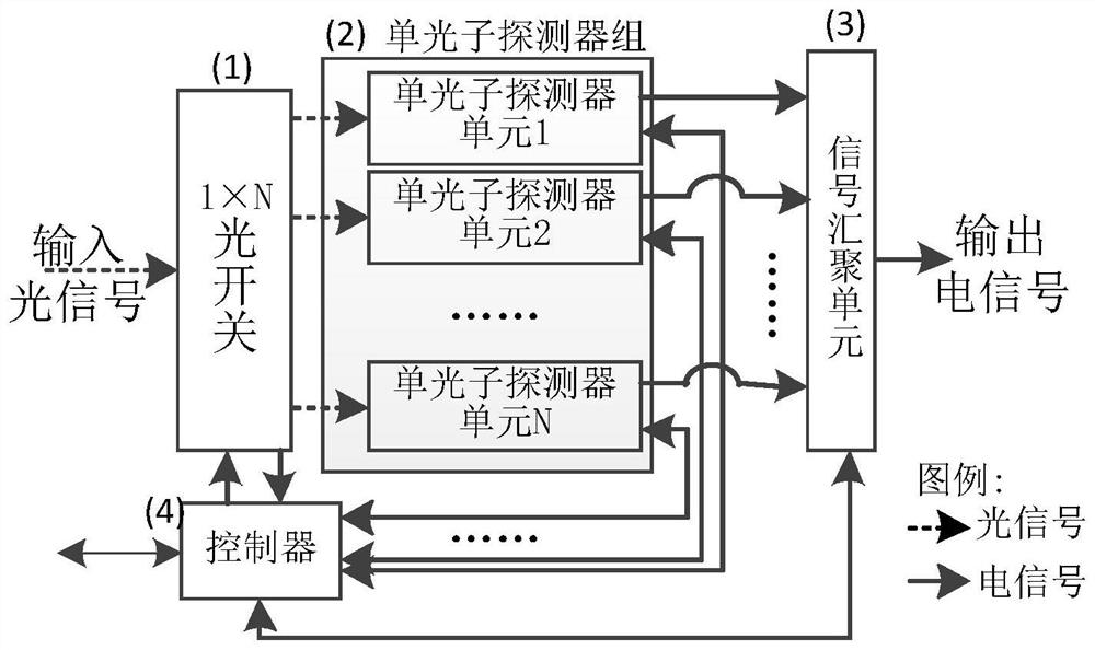
[0087] Image 6 It shows the structure diagram of the single photon detector system in which the detection dead time is shortened to 1 / 4 in Embodiment 1 of the present invention, as Image 6 As shown: the system may include: a 1×4 optical switch 1, a single photon detector group 2, a signal aggregation unit 3 and a controller 4;
[0088] The 1×4 optical switch 1, the single photon detector group 2 and the signal convergence unit 3 are sequentially connected;
[0089] The controller 4 is respectively connected to the 1×4 optical switch 1, the single photon detector group 2 and the signal convergence unit 3;
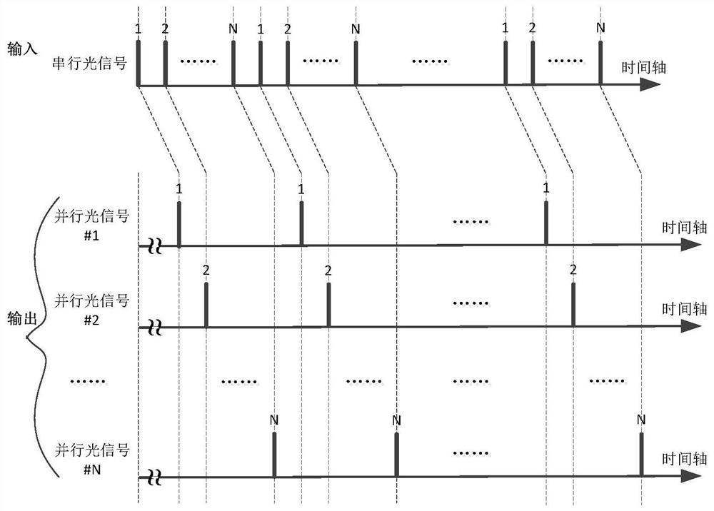
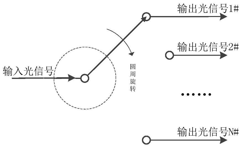
[0090] The 1×4 optical switch 1 is used to complete the serial / parallel conversion of optical signals; the single photon detector group 2 is used to convert parallel optical signals into parallel electrical signals;
[0091] The signal convergence unit 3 is used to complete parallel / serial conversion of electrical signals;
[0092] The controller 4 is used to control the ...
Embodiment 2
[0114] Figure 8 It shows the structure diagram of the single photon detector system whose detection dead time is shortened to one sixteenth in Embodiment 1 of the present invention, as Figure 8 As shown: the system may include: a 1×16 optical switch 1, a single photon detector group 2, a signal aggregation unit 3 and a controller 4;
[0115] The 1×16 optical switch 1, the single photon detector group 2 and the signal convergence unit 3 are sequentially connected;
[0116] The controller 4 is respectively connected to the 1×16 optical switch 1, the single photon detector group 2 and the signal convergence unit 3;
[0117] The 1×16 optical switch 1 is used to complete the serial / parallel conversion of optical signals; the single photon detector group 2 is used to convert parallel optical signals into parallel electrical signals;
[0118] The signal convergence unit 3 is used to complete parallel / serial conversion of electrical signals;
[0119] The controller 4 is used to c...
Embodiment 3
[0141] Figure 9 It shows the single photon detector system diagram in which the detection dead time of Embodiment 1 of the present invention is shortened to one sixty-fourth, as Figure 9 As shown, the system may include: a 1×64 optical switch 1, a single photon detector group 2, a signal aggregation unit 3 and a controller 4;
[0142] The 1×64 optical switch 1, the single photon detector group 2 and the signal convergence unit 3 are sequentially connected;
[0143] The controller 4 is respectively connected to the 1×64 optical switch 1, the single photon detector group 2 and the signal convergence unit 3;
[0144] The 1×64 optical switch 1 is used to complete the serial / parallel conversion of optical signals; the single photon detector group 2 is used to convert parallel optical signals into parallel electrical signals;
[0145] The signal convergence unit 3 is used to complete parallel / serial conversion of electrical signals;
[0146] The controller 4 is used to control ...
PUM
 Abstract
Description
Claims
Application Information
 - R&D Engineer
- R&D Manager
- IP Professional
- Industry Leading Data Capabilities
- Powerful AI technology
- Patent DNA Extraction
Browse by: Latest US Patents, China's latest patents, Technical Efficacy Thesaurus, Application Domain, Technology Topic, Popular Technical Reports.
© 2024 PatSnap. All rights reserved.Legal|Privacy policy|Modern Slavery Act Transparency Statement|Sitemap|About US| Contact US: help@patsnap.com