Adjacent space electric power patch

A near-space, electric power technology, used in motor vehicles, lighter-than-air aircraft, aircraft, etc., can solve problems such as high thrust lower limit, high noise, and inability to actively control, achieve no-torque balance requirements, and low infrared visibility. , simple design effect

Active Publication Date: 2021-02-05
NANJING UNIV OF AERONAUTICS & ASTRONAUTICS
View PDF6 Cites 0 Cited by
  • Summary
  • Abstract
  • Description
  • Claims
  • Application Information

AI Technical Summary

Problems solved by technology

[0002] At present, the power approach of low-speed aircraft in near space mainly includes the following aspects: (1) Propeller power: It is characterized by the use of propellers with large diameters, which are powered by electricity or fuel to obtain greater thrust near a height of 20km, such as high-altitude The propeller of the airship; the main advantage is that the thrust is large, which can reach more than several thousand cattle. The main disadvantage is that the noise is relatively large, and as the altitude increases, the density of the atmosphere decreases, and the power provided by the propeller decreases rapidly; (2) wind power: Its characteristic is to use the atmospheric wind field in the adjacent space, and the power is formed by the atmospheric wind field, such as a hot air balloon or a stratospheric balloon; the main advantage is that it does not need to consume additional energy, and the main disadvantage is that it cannot be actively controlled, so it is difficult to completely offset the influence of the atmospheric wind field; (3) Jet power: It is characterized by the use of gas combustion expansion or heating expansion to form a strong power, which is mostly used in high-speed aircraft, such as ramjet engines; the main advantage is that it can form strong power, such as reaching tens of thousands of cattle. , and easy to control, the main disadvantage is that the lower limit of thrust is high, usually above several thousand cattle, and it needs to consume fuel continuously, so it cannot maintain long-term voyage

Method used


Image

  • Adjacent space electric power patch
  • Adjacent space electric power patch
  • Adjacent space electric power patch

Examples


Embodiment 2

[0025] Embodiment 2 is attached Figure 4 As shown, the material of each part is the same as that of Embodiment 1, but the embodiment 2 increases the cathode wire 401 and the anode wire 407 of the inner ring in structure; The bottom of the base 406 penetrates and passes through from their other side; the insulating rivets passing through the cathode base 405 and the anode base 406 are reduced to one, so the fixing is also increased between the cathode base 405 and the anode base 406 Insulated rivets 404 for location.

[0026] In Embodiment 2, the number of cathode wires 401 and anode wires 407 in the inner ring can be determined according to the size of the electrodynamic patch, and a distance of 1 cm to 2 cm is usually maintained between the inner and outer rings of the cathode wire 401 or anode wire 407; The number of loops may be less than or equal to the number of loops in the anode wire 407 .

[0027] The connection mode of embodiment 2 is the same as that of embodiment...

Embodiment 3

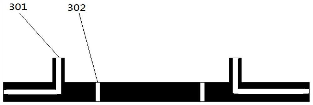
[0028] Embodiment 3 is attached Figure 5 As shown, the materials of each component are the same as in Embodiment 1, the cathode wire 501 and the anode wire 507 penetrate through the bottom of the lower insulating layer 508, pass through the cathode base 504 and the anode base 505, and pass through the upper insulating layer 506, Keep vertical to the surface of the upper insulating layer, and the height on the surface of the upper insulating layer is 1mm to 3cm; there are no lead holes on the left and right sides of the cathode base 504 and the anode base 505, but the top circular tube vertically penetrates the bottom to form Through holes: Insulation rivets 503 are located between the round tubes of the cathode base 504 and the anode base 505 except that the four corners of the patch remain unchanged.

[0029] The connection mode of embodiment 3 is the same as that of embodiment 1, the anode wire 507 is connected to the output terminal of the high voltage power supply, and th...


PUM

PropertyMeasurementUnit
diameteraaaaaaaaaa
thicknessaaaaaaaaaa

Abstract

The invention discloses an electrodynamic patch near space, comprising: an anode wire, a cathode wire, an anode base, a cathode base, an insulating patch, an upper insulating sheet, a lower insulating sheet and an insulating rivet. The beneficial effects of the present invention are: (1) The electrodynamic patch can be adhered to the outer layer of a low-speed aircraft without requiring an independent space like a propeller, and as the adhesion area increases, the thrust increases, which is especially suitable for large-scale low-speed airships such as stratospheric airships. Aircraft; (2) Within the altitude of 20km to 50km, as the altitude increases, the thrust of the electrodynamic patch with the same voltage will continue to increase; (3) The electrodynamic patch has no mechanical movement, no noise, and low infrared visibility; (4) Compared with the existing propulsion devices such as high-altitude propellers, the electric power patch is lighter in weight, simpler in design, and has no requirement for rotational torque balance.

Description

technical field [0001] The invention relates to the technical field of near-space low-speed aircraft power, in particular to a near-space electrodynamic patch. Background technique [0002] At present, the power approach of low-speed aircraft in near space mainly includes the following aspects: (1) Propeller power: It is characterized by the use of propellers with large diameters, which are powered by electricity or fuel to obtain greater thrust near a height of 20km, such as high-altitude The propeller of the airship; the main advantage is that the thrust is large, which can reach more than several thousand cattle. The main disadvantage is that the noise is relatively large, and as the altitude increases, the density of the atmosphere decreases, and the power provided by the propeller decreases rapidly; (2) wind power: Its characteristic is to use the atmospheric wind field in the adjacent space, and the power is formed by the atmospheric wind field, such as a hot air ballo...

Claims


Application Information

Patent Timeline
Patent Type & Authority Patents(China)
IPC IPC(8): B64B1/00B64B1/24
CPCB64B1/00B64B1/24
Inventor 全荣辉周凯方美华
Owner NANJING UNIV OF AERONAUTICS & ASTRONAUTICS
Why Eureka
Try Eureka