
Differential multi-shaft cascade electromechanical coupling device for hybrid electric vehicles

A technology of hybrid electric vehicles and electromechanical coupling, which is applied to the arrangement of multiple prime movers of power plants, pneumatic power plants, and general power plants, and can solve the problems of difficult integration, low efficiency, and slow development of hybrid electric vehicles. and other problems, to meet the high-speed demand, the effect of simple structure

Active Publication Date: 2020-11-03
CHONGQING JIAOTONG UNIVERSITY
View PDF7 Cites 0 Cited by
  • Summary
  • Abstract
  • Description
  • Claims
  • Application Information

AI Technical Summary

Problems solved by technology

[0002] At present, the production and sales of hybrid electric vehicles are gradually increasing. Foreign companies such as THS of Toyota, FHS of Ford, and AHS of General Motors have widely used hybrid power transmission systems. However, there are few core patents and products in my country, so Leading to the slow development of hybrid vehicles in China
At present, the transmission system of hybrid electric vehicles generally faces problems such as low efficiency and difficulty in integration. As the main component of the transmission system of hybrid electric vehicles, the electromechanical coupling device is particularly important to improve its mechanical efficiency.

Method used


Image

  • Differential multi-shaft cascade electromechanical coupling device for hybrid electric vehicles
  • Differential multi-shaft cascade electromechanical coupling device for hybrid electric vehicles
  • Differential multi-shaft cascade electromechanical coupling device for hybrid electric vehicles

Examples


Embodiment Construction

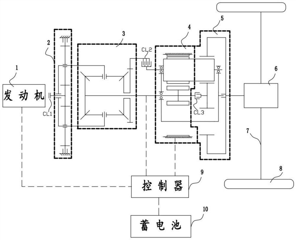
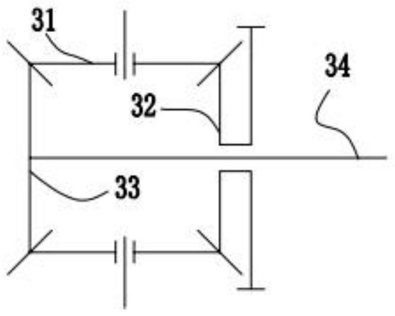
[0019] See figure 1 , The mechanism diagram of the differential multi-shaft-stage online electrical coupling device includes engine 1, first-stage planetary row 2, two-stage differential bevel gear planetary row 3, multi-shaft double-rotor motor 4, three-stage planetary row 5, differential Speed ​​gear 6, three control components CL1, CL2, CL3, half shaft 7, wheels 8, engine and dual-rotor motor integrated controller 9, and battery 10.

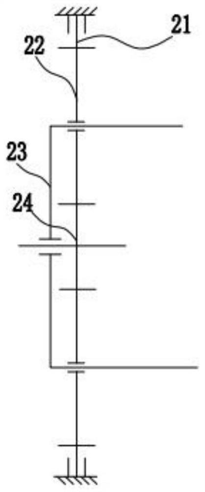
[0020] See figure 2 The first-stage planetary row includes a first-stage planetary row gear ring 21, a first-stage planetary row planetary gear 22, a first-stage planetary row planet carrier 23, and a first-stage planetary row sun gear 24. The engine power is transmitted through the first-stage planetary row sun gear 24 through the first-stage planetary row planetary gear 23. Since the first-stage planetary row planet carrier 22 is only connected with the second-stage differential bevel gear planetary gear 31, the gear ring 21 is restricted. Deg...


PUM


Abstract

The invention discloses a differential multi-axis cascade mechanical-electrical coupling device for a hybrid power vehicle. The coupling device comprises an engine, a first-stage planet row, a second-stage differential bevel gear planet row, a multi-axis dual-rotor motor, a third-stage planet row and a differential mechanism. The engine and the multi-axis cascade dual-rotor motor are coupled according to the differential principle of the differential mechanism, and therefore the problems that in the prior art, a transmission system is complicated, control difficulty is large and integration isnot easy are solved. The dual-rotor motor serves as one part of the mechanism and is in multi-axis cascade connection with the mechanism, and mechanism characteristics of the device are sufficientlymined; in combination with different clutches, the coupling device can have various operating modes and is suitable for various complicated working conditions, the working conditions of the engine aregreatly improved so that the engine can work in a high-efficiency region, and the vehicle operates under ideal working conditions.

Description

Technical field [0001] The invention relates to the technical field of automobile power transmission, in particular to a differential multi-shaft-stage online electrical coupling device for hybrid electric vehicles. Background technique [0002] At present, the production and sales of hybrid vehicles are gradually increasing. Foreign companies such as Toyota's THS, Ford's FHS, GM's AHS and other companies have introduced hybrid power transmission systems that have been widely used, while domestic core patents and products are less. As a result, the development of hybrid vehicles in my country is relatively slow. At present, the transmission system of hybrid electric vehicles generally faces problems such as low efficiency and greater difficulty in integration. As the main component of the hybrid electric vehicle transmission system, the electromechanical coupling device is particularly important to improve its mechanical efficiency. [0003] The multi-axis stage on-line electrical ...

Claims


Application Information

Patent Timeline
Patent Type & Authority Patents(China)
IPC IPC(8): B60K6/365B60K6/26
CPCB60K6/26B60K6/365
Inventor 邓涛唐鹏李鑫尹燕莉
Owner CHONGQING JIAOTONG UNIVERSITY
Learn More