
Motor coil winding device based on crank slider mechanism principle

A technology of a crank slider mechanism and a winding device, which is applied in the direction of electromechanical devices, manufacturing motor generators, electrical components, etc., can solve the problems of poor product quality, low winding efficiency, and high labor intensity, so as to improve winding efficiency, The effect of improving product quality and reducing labor intensity

Pending Publication Date: 2018-07-03
德州恒力电机有限责任公司
View PDF6 Cites 0 Cited by
  • Summary
  • Abstract
  • Description
  • Claims
  • Application Information

AI Technical Summary

Problems solved by technology

[0003] The technical problem to be solved by the present invention is: in order to overcome the defects of low winding efficiency, poor product quality and high labor intensity in the winding process of the motor coil mold in the prior art, the present invention provides a The motor coil winding device, through the change of the distance between the upper and lower winding dies caused by the reciprocating linear motion of the slider mechanism, completes the winding of the motor coils without assembling or disassembling the winding dies

Method used


Image

  • Motor coil winding device based on crank slider mechanism principle
  • Motor coil winding device based on crank slider mechanism principle
  • Motor coil winding device based on crank slider mechanism principle

Examples


Embodiment Construction

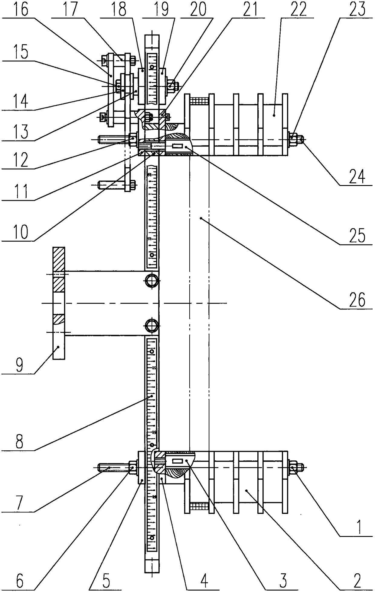
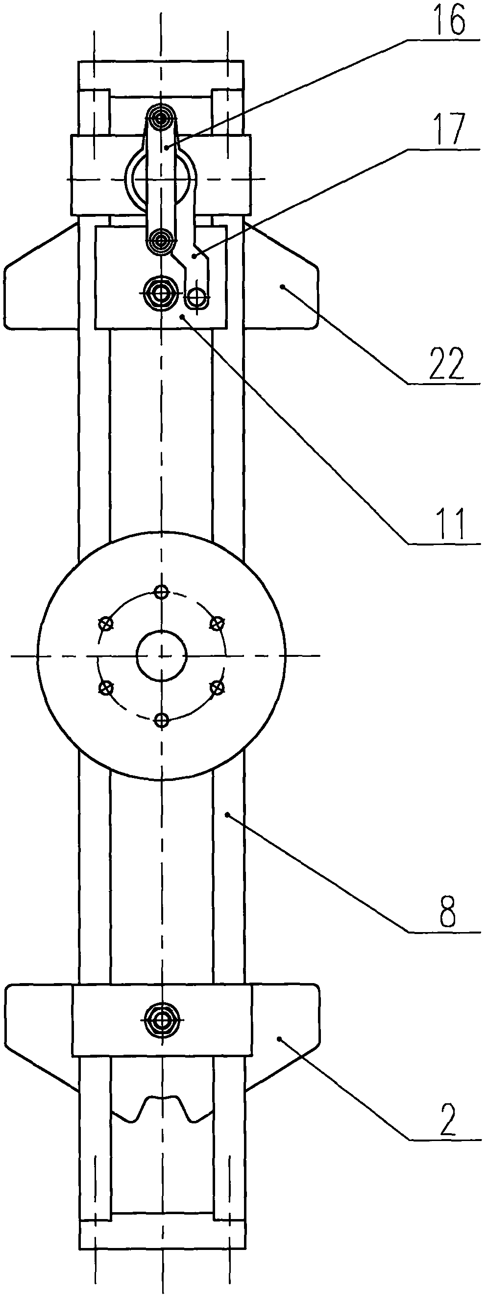
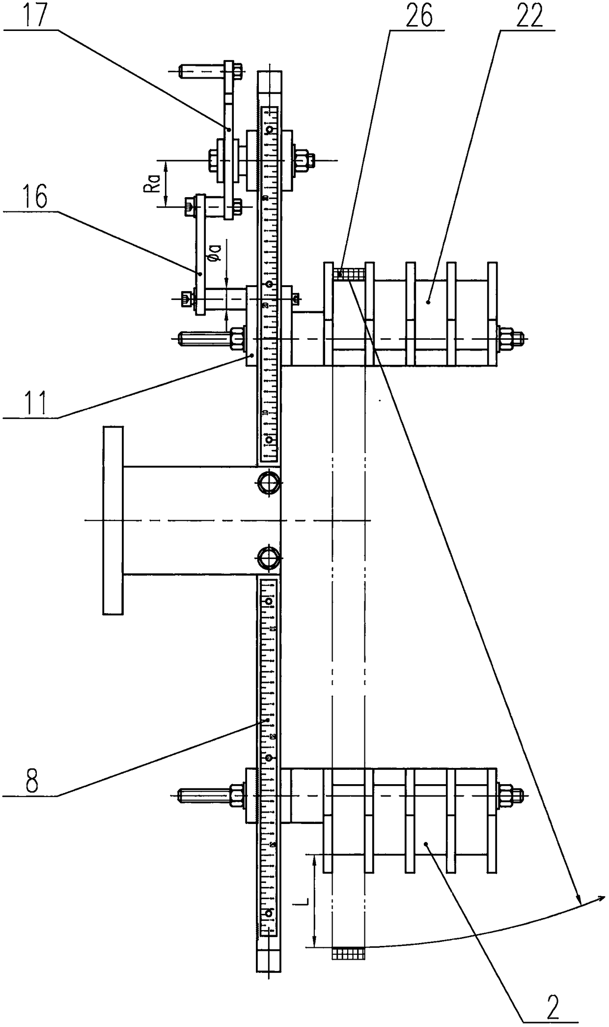
[0037] The present invention will be described in further detail below. see Figure 1 to Figure 27, a motor coil winding device based on the principle of a crank slider mechanism consists of a lower winding die 2, a winding frame 8, a lower winding die fixing mechanism, a winding frame seat 9, a slider mechanism, a connecting rod 16, and a crank plate 17, the crank disc supporting mechanism and the upper winding die 22 are formed. The lower winding die fixing mechanism, the crank disk support mechanism and the winding frame 8 are connected by threads to form a fixed part of the crank slider mechanism——frame. Crank plate 17, connecting rod 16, slider mechanism are crank, connecting rod and slide block of crank slider mechanism respectively. The upper winding die 22 and the lower winding die 2 are respectively assembled on the slider mechanism and the lower winding die fixing mechanism. The fast switching between the winding state and the unloading state of the winding device...


PUM


Abstract

The invention discloses a motor coil winding device based on a crank slider mechanism principle. The device is formed by a winding frame seat, a winding frame, a lower winding mold fixing mechanism, acrank disk supporting mechanism, a crank disk, a connecting rod, a slider mechanism and upper and low winding molds. Winding molds are formed by upper and lower parts, and the sizes of the winding molds determine the size of an end of a motor coil. The upper and low winding molds are assembled to a slider and a frame of a crank slider mechanism. According to the crank slider mechanism principle,when the slider makes a reciprocating linear motion, the pitch of the upper and lower winding molds is changed, and the quick switching of a winding state and an unloading state of the winding deviceis realized without assembling or disassembling the winding molds. The labor intensity is reduced while the winding efficiency and coil quality are improved. By setting different winding state distances of the upper and low winding molds, motor coils with the same end part size and different linear side lengths can be wound, and the versatility of the motor coil winding device is achieved.

Description

technical field [0001] The invention belongs to the technical field of motor manufacturing and relates to the improvement of a motor coil winding die. Background technique [0002] The motor coil is an important part of the motor, and its size and quality are determined by the motor coil winding device. Whether the design of the motor coil winding device is reasonable or not directly affects the manufacturing cost, efficiency and quality of the motor coil. The high efficiency and versatility of the motor coil winding device are more and more valued by motor manufacturers. For the existing motor coil winding device, a general-purpose winding die has been designed for the diversity of motor types and the uncertainty of the coil circumference in the research and development stage. For example, the Chinese utility model patent whose authorized notification number is CN204517594 U discloses "a winding template for motor". The invention patent application with the application p...

Claims


Application Information

Patent Timeline
Patent Type & Authority Applications(China)
IPC IPC(8): H02K15/04
CPCH02K15/045
Inventor 申洪彬张明巩方彬
Owner 德州恒力电机有限责任公司
Learn More