Transfer system for transporting bogies
A bogie and transport track technology, applied in the field of transport systems for transport bogies, can solve problems such as low maintenance efficiency, and achieve the effects of being beneficial to service life, improving safety factor, and improving transport efficiency
- Summary
- Abstract
- Description
- Claims
- Application Information
AI Technical Summary
Problems solved by technology
Method used
Image
Examples
Embodiment 1
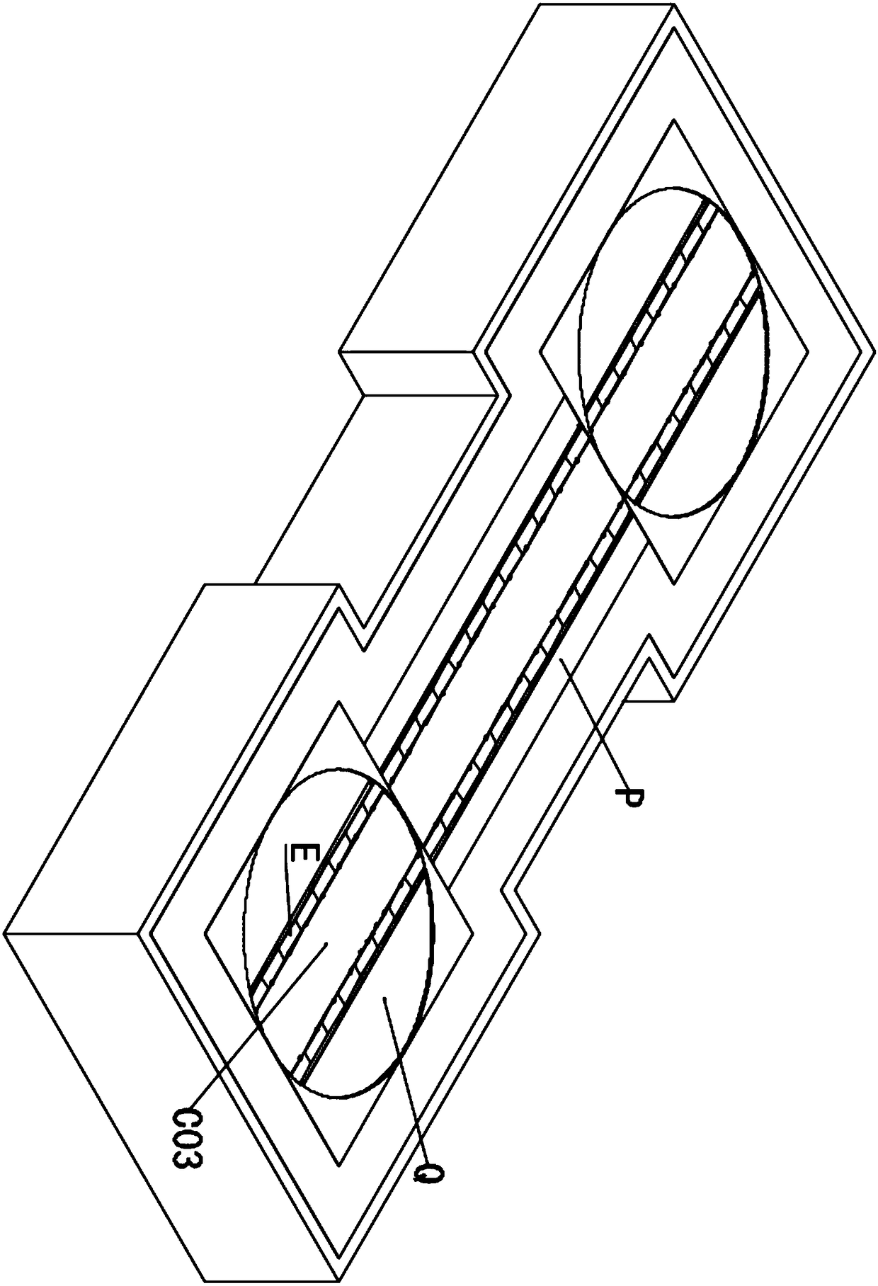
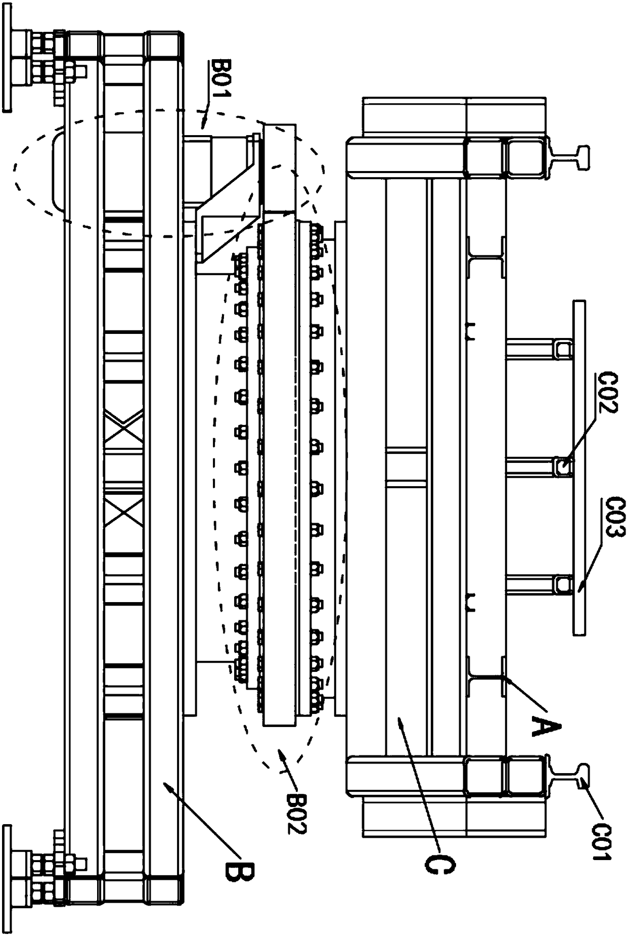
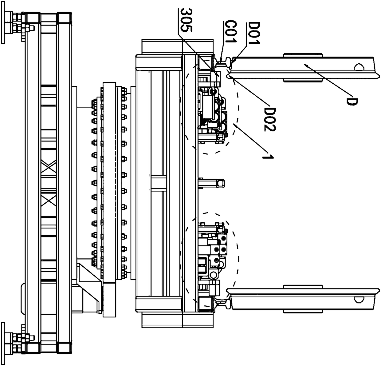
[0046] like Figure 1~5 As shown, a transfer system for transporting bogies includes a turntable Q and a straight track P, and the first track C01 for transporting a bogie is arranged on the turntable Q and the straight track P, wherein the One side of the first track C01 is provided with a transportation track A used in conjunction with the first track C01, and the vehicle body 1 for pushing the bogie is installed on the transportation track A.
[0047] More optimally, the turntable Q and the straight track P are fixedly connected by bolts, the first track C01 is symmetrically arranged in two on the horizontal plane, the transport track A is arranged between the two first track C01, and There are also two transport rails A arranged symmetrically in the horizontal plane; one car body 1 is installed on each of the two transport rails A of each straight track P, and one car body is installed on each of the two transport rails A of each turntable Q 1.
[0048] Further, the turn...
Embodiment 2
[0058] like Image 6 and Figure 10 As shown, this embodiment is further optimized on the basis of Embodiment 1. Specifically, two crank-slider mechanisms for pushing the bogie are fixed on the car body 1, and the crank-slider mechanisms are divided into A first slider crank mechanism and a second slider crank mechanism.
[0059]Further, the first slider crank mechanism includes a first hydraulic cylinder and a sliding arm fixed on the vehicle body, the rod end of the first hydraulic rod of the first hydraulic cylinder is connected with a first slider, and the first The slider is sleeved on the sliding arm, and the first slider is connected with a first sliding rod, and the end of the first sliding rod far away from the first slider is connected with a first rotating rod, and the first The connection between the sliding rod and the first rotating rod is located on the first rotating rod between the two ends of the first rotating rod, one end of the first rotating rod is conn...
Embodiment 3
[0068] like Figure 7-9 As shown, this embodiment is further optimized on the basis of Embodiment 2. Specifically, the transportation track A is set as an "I"-shaped structure, and the transportation track A includes a flange plate A01 and a web A02.
[0069] Further, the lower end of the car body 1 is provided with a traveling chamber 2 used in conjunction with the "I"-shaped transport rail A, and the traveling chamber 2 is provided with a transmission wheel 904, a positioning wheel 201 and a brake lever 601, and The transmission wheel 904 is arranged at the position close to the upper end in the walking chamber 2, and the positioning wheels 201 are arranged symmetrically on the opposite side walls of the walking chamber 2, and the distance between the two opposite positioning wheels 201 is greater than that of the abdomen. The thickness of the plate A02, the distance between the upper rim of the positioning wheel 201 and the lower rim of the transmission wheel 904 is greate...
PUM
 Abstract
Description
Claims
Application Information
 - R&D
- Intellectual Property
- Life Sciences
- Materials
- Tech Scout
- Unparalleled Data Quality
- Higher Quality Content
- 60% Fewer Hallucinations
Browse by: Latest US Patents, China's latest patents, Technical Efficacy Thesaurus, Application Domain, Technology Topic, Popular Technical Reports.
© 2025 PatSnap. All rights reserved.Legal|Privacy policy|Modern Slavery Act Transparency Statement|Sitemap|About US| Contact US: help@patsnap.com


