
Cooling device with air passage circulation of new energy vehicle

A new energy vehicle and cooling device technology, which is applied in the combination of power unit cooling layout, power unit, heating/cooling equipment, etc., can solve the problems of large power consumption, poor heat dissipation, and increased battery load, etc., and achieve reduction Noise, easy disassembly and installation, and the effect of increasing inflow

Inactive Publication Date: 2018-07-03
黄邦擎
View PDF0 Cites 1 Cited by
  • Summary
  • Abstract
  • Description
  • Claims
  • Application Information

AI Technical Summary

Problems solved by technology

[0002] With the rapid development of the economy, people have realized the damage to the environment caused by the rapid economic development. In recent years, the smog in our country has become more and more serious. Vigorously support the research and development of new energy vehicles. New energy vehicles can reduce carbon dioxide emissions and protect the environment. However, the cooling device of new energy vehicles is currently a device that needs to be improved. Most of the heat dissipation devices of traditional new energy vehicles are carried out by the air conditioning system inside the car. Cooling, which will increase the load on the battery, often consumes a lot of power, and the heat dissipation effect is not good, which can no longer meet the existing market demand

Method used


Image

  • Cooling device with air passage circulation of new energy vehicle
  • Cooling device with air passage circulation of new energy vehicle
  • Cooling device with air passage circulation of new energy vehicle

Examples


Embodiment Construction

[0014] The following will clearly and completely describe the technical solutions in the embodiments of the present invention with reference to the accompanying drawings in the embodiments of the present invention. Obviously, the described embodiments are only some, not all, embodiments of the present invention. Based on the embodiments of the present invention, all other embodiments obtained by persons of ordinary skill in the art without making creative efforts belong to the protection scope of the present invention.

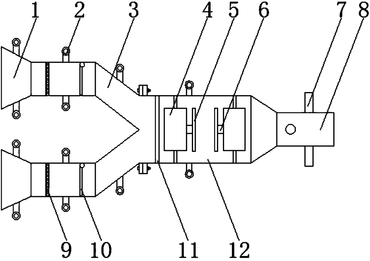
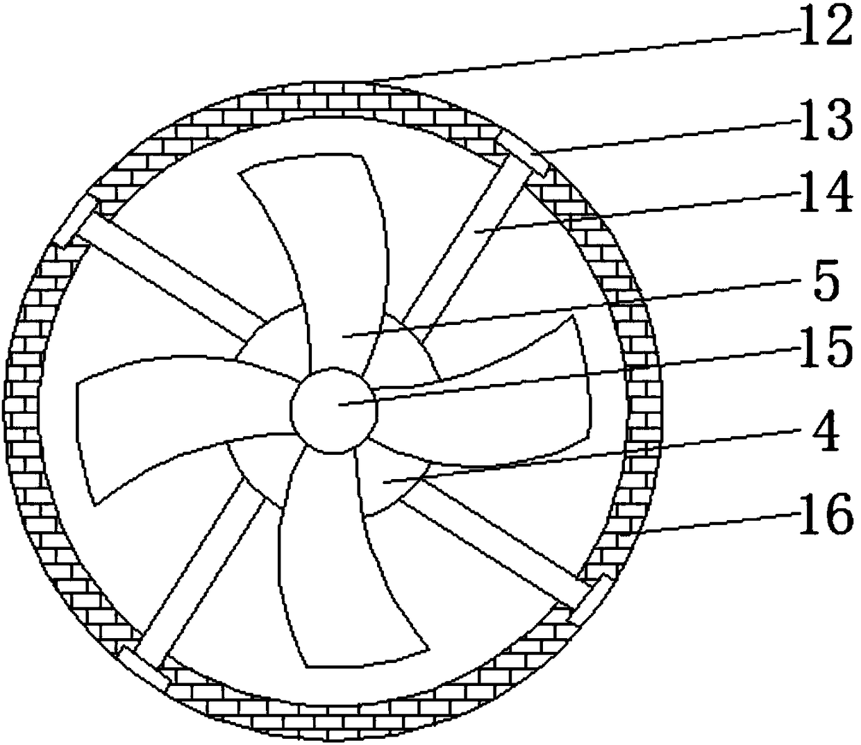
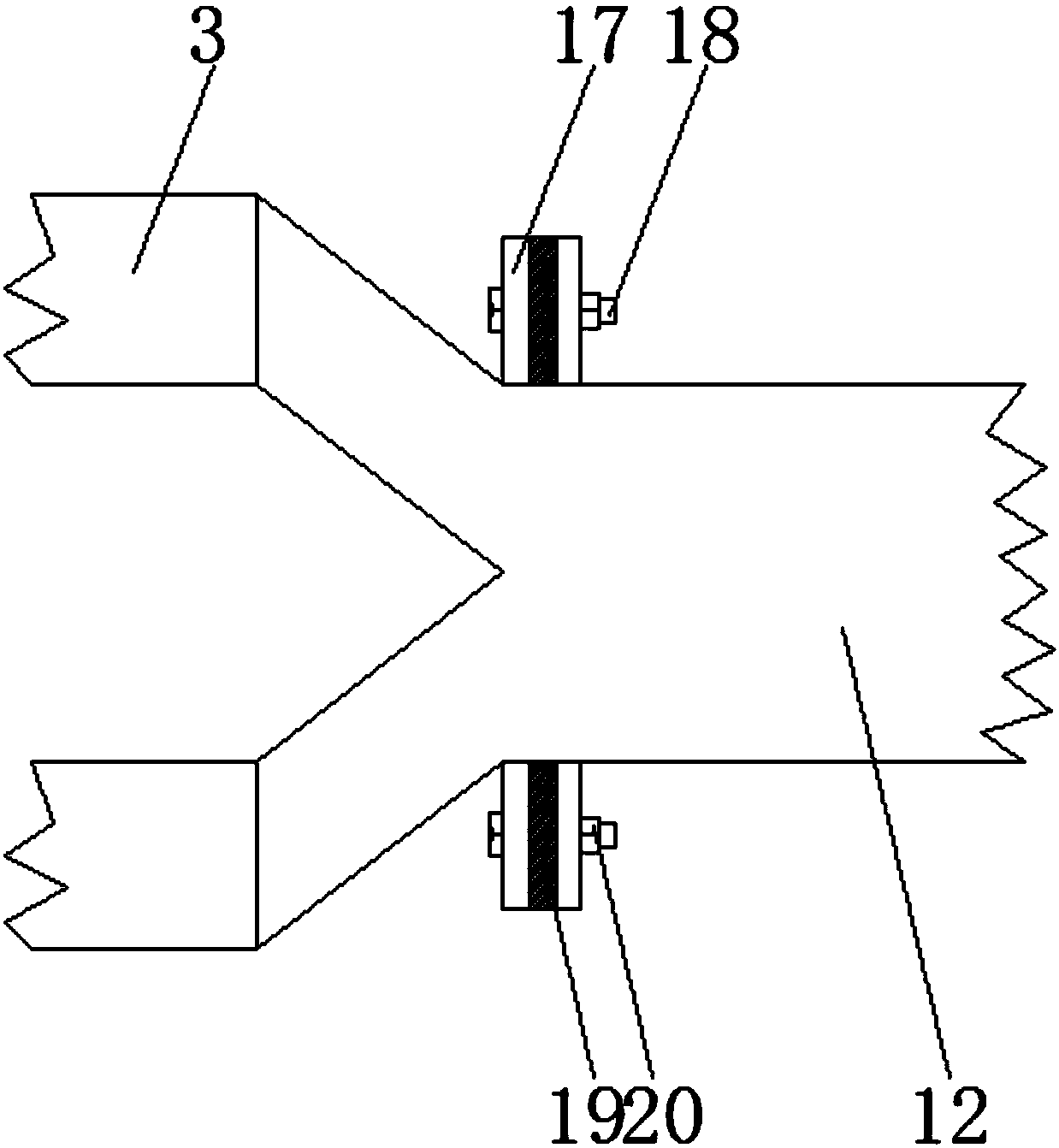
[0015] see Figure 1-3 , an embodiment provided by the present invention: a cooling device with air duct circulation for a new energy vehicle, including a ventilation pipe A3 and a motor 4, the ventilation pipe A3 and the air inlet 1 are in a sealed connection, and the inside of the ventilation pipe A3 Coarse-hole filter screen 9 and damper 10 are set, and the flange 17 at the right end of the pipe A3 is connected with the flange 17 at the left end of the vent...


PUM


Abstract

The invention discloses a cooling device with air passage circulation of a new energy vehicle. The cooling device comprises air ducts A and electric motors, wherein the air ducts A are in sealed connection with air inlets; flanges at the right ends of the air ducts A are connected with the flanges at the left end of an air duct B by fastening bolts; each gasket is arranged between the two corresponding flanges; fixing ring lugs are mounted on the two sides of each air duct A and the two sides of the air duct B; the right end of the air duct B is in sealed connection with an air outlet providedwith connecting pipes; connecting rods fixed to the electric motors are fixedly connected to the inner wall of the air duct B by fixing blocks; a soundproof pad is mounted at the inner wall of the air duct B; rotating shafts mounted on the electric motors are fixedly connected to impeller mounting plates; impellers are fixed on the impeller mounting plates; and a fine pore filter screen on the left side of the electric motors is fixed to the inner wall of the air duct B. The cooling device with the air passage circulation of the new energy vehicle is capable of utilizing natural wind to coolthe new energy vehicle by virtue of the air inlets and the air ducts, saves energy and is free of pollution.

Description

technical field [0001] The invention relates to the technical field of new energy vehicles, in particular to a cooling device for a new energy vehicle with air duct circulation. Background technique [0002] With the rapid development of the economy, people have realized the damage to the environment caused by the rapid economic development. In recent years, the smog in our country has become more and more serious. Vigorously support the research and development of new energy vehicles. New energy vehicles can reduce carbon dioxide emissions and protect the environment. However, the cooling device of new energy vehicles is currently a device that needs to be improved. Most of the heat dissipation devices of traditional new energy vehicles are carried out by the air conditioning system inside the car. Cooling, which will increase the load on the battery, often consumes a lot of power, and the heat dissipation effect is not good, which can no longer meet the existing market dem...

Claims


Application Information

Patent Timeline
IPC IPC(8): B60H1/00B60H3/06
CPCB60H1/00B60H3/06B60K11/06B60H1/00385B60H1/00464B60H3/0608
Inventor 黄邦擎
Owner 黄邦擎
Learn More