Stent Graft

A technology of covered stents and bare stents, applied in stents, medical science, blood vessels, etc., can solve problems such as stent rupture and stent isolation function failure, and achieve the effect of inhibiting expansion and reducing the risk of failure

Active Publication Date: 2020-05-05
LIFETECH SCIENTIFIC (SHENZHEN) CO LTD
View PDF8 Cites 0 Cited by
  • Summary
  • Abstract
  • Description
  • Claims
  • Application Information

AI Technical Summary

Problems solved by technology

[0003] Although the existing invasive double-layer ePTFE / PTFE / FEP covered stent can reduce the ion release of the connecting rod of the stent and strengthen the biocompatibility between the stent and the inner wall of the blood vessel to a certain extent, the ePTFE / PTFE / FEP covered stent (such as figure 1 The adventitia 802 and the intima 800 in the stent) have certain ductility in the circumferential direction, and after being impacted by high-pressure blood flow for a long time, the stent (such as figure 1 Both the bare stent 801) and the ePTFE / PTFE / FEP coating will expand to a certain extent, and in severe cases, the coating will rupture, and the isolation function of the stent will fail.

Method used


Image

  • Stent Graft
  • Stent Graft
  • Stent Graft

Examples


Embodiment 1

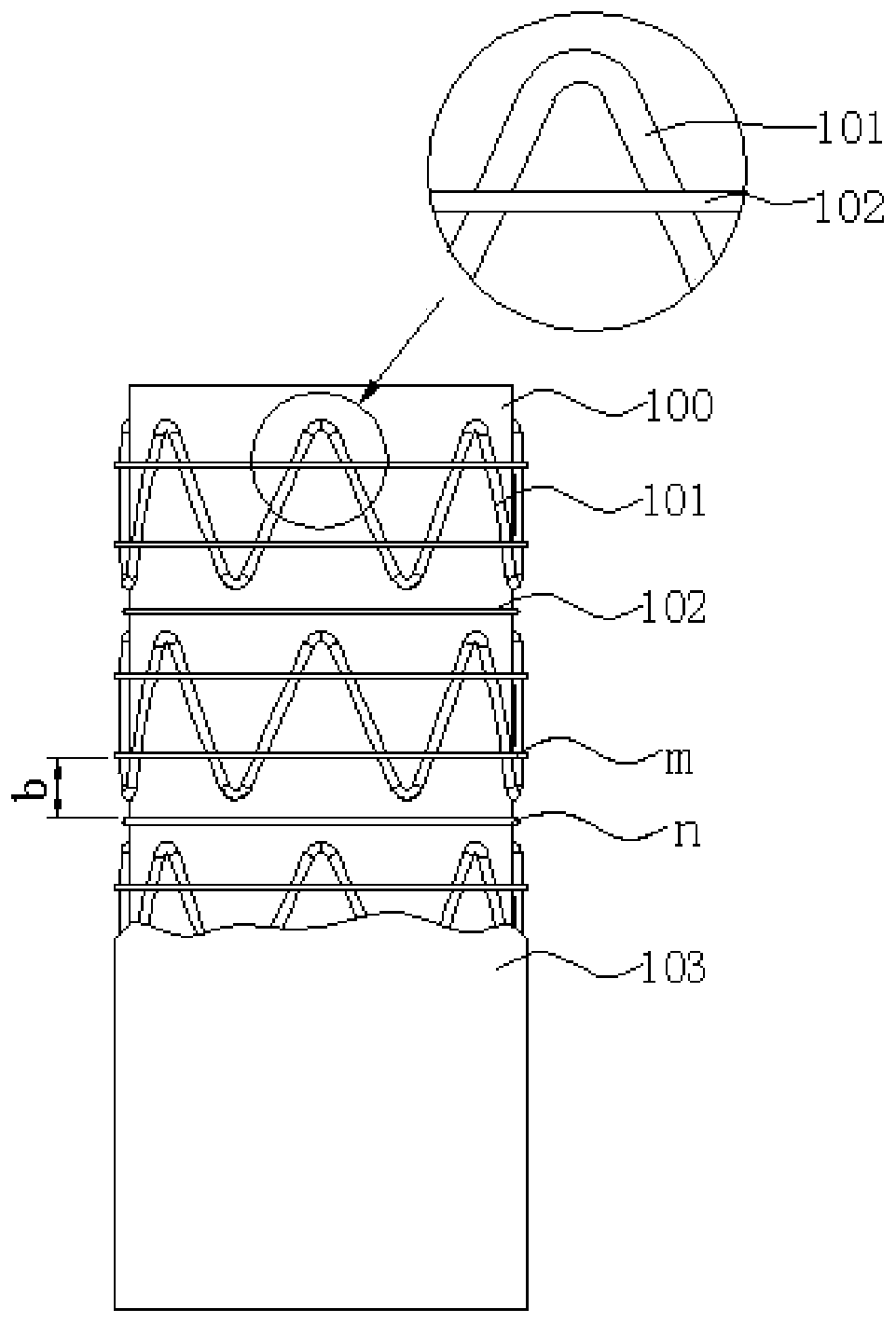
[0049] See figure 2 , a covered stent, comprising an ePTFE inner membrane 100, an ePTFE outer membrane 103, and a self-expandable bare stent 101 disposed between the ePTFE outer membrane 103 and the ePTFE inner membrane 100. The self-expanding bare stent 101 is composed of a plurality of Z-shaped wave coils arranged at intervals along the longitudinal central axis direction of the stent-graft (that is, the axial direction of the stent-graft), and the adjacent upper and lower Z-shaped wave coils do not contact each other; Between the ePTFE outer membrane 103 and the ePTFE inner membrane 100 is arranged a ring-shaped pre-tightened winding PTFE wire 102 . The vertical distance b between two adjacent sections of PTFE wire m and PTFE wire n is in the range of 1-30 mm, preferably 2-12 mm. The PTFE wire 102 is pre-tightened and wound around the outer surface of the self-expandable bare stent 101 in a ring shape (such as figure 2 m) and the outer surface of the ePTFE inner membran...

Embodiment 2

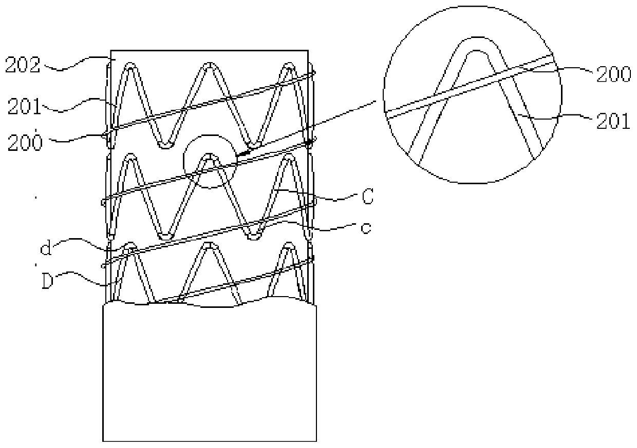
[0056] See image 3 The structure of the stent-graft in this embodiment is similar to that of the stent-graft in Example 1, the only difference is that the PTFE wire 200 is pre-tightened and wound in the outer surface of the self-expandable bare stent 201 and inside the ePTFE in a helical shape. on the outer surface of the membrane 202.

[0057] It should be noted that when the PTFE wire 200 is helically wound on the inner or outer surface of the self-expandable bare stent 201, the PTFE wire 200 can be wound from the corrugated coil C of the self-expandable bare stent 201 to the corrugated coil C. Adjacent wave circle D. For example, see again image 3 , the PTFE wire 200 is wound from the outer surface of the corrugated coil C at the position c of the trough c to the outer surface of the corrugated coil D adjacent to the corrugated coil C at the position d of the crest.

[0058] It can be understood that in other embodiments, the PTFE wire 200 can also be multi-segment or ...

Embodiment 3

[0060] See Figure 4 The structure of the stent-graft in this embodiment is similar to the structure of the stent-graft in Embodiment 1, the only difference is that the PTFE wire 300 in this embodiment is pre-tightened in a ring and wrapped around the inner surface of the self-expanding bare stent 301 and On the outer surface of the inner membrane 302 of ePTFE.


PUM


Abstract

A covered stent, comprising an outer membrane (103), an inner membrane (100) and a bare stent (101) which is disposed between the outer membrane (103) and the inner membrane (100), at least one tying wire (102) being disposed on an outer surface of the outer membrane (103) or / and between the outer membrane (103) and the inner membrane (100). The tying wire (102) is wound in a ring or a spiral shape about an outer surface of the bare stent (101), an inner surface of the bare stent (101) or an outer surface of the inner membrane (100); or the tying wire (102) passes between an inner surface and an outer surface of two connection rods of the bare stent (101). By using an anti-extension function of the tying wire (102) and by means of a coating means of the tying wire (102), a covered stent is effectively prevented from expanding under the impact of high pressure blood flow, thereby reducing the risk of function loss of the covered stent due to the expansion of the covered stent.

Description

technical field [0001] The invention relates to the technical field of interventional medical devices, in particular to a covered stent. Background technique [0002] The covered stents currently on the market generally include a bare stent and a single-layer PET film structure or a double-layer ePTFE / PTFE film structure arranged on the bare stent. These covered stents isolate the blood flow from the lesion through the covering, and eliminate the influence of blood pressure on the lesion, so as to achieve the purpose of healing. After the single-layer PET covered stent is implanted in the body, the connecting rod of the bare stent of the covered stent will be directly exposed in the blood, and the metal ions released by the connecting rod (such as nickel ions released by the nickel-titanium alloy stent in the blood) enter the blood In the circulation, it will cause adverse effects on the human body, such as carcinogenic and so on. The single-layer PET membrane structure is...

Claims


Application Information

Patent Timeline
Patent Type & Authority Patents(China)
IPC IPC(8): A61F2/07
CPCA61F2/0077A61F2/07A61F2002/075A61F2210/00A61F2/82
Inventor 肖本好何里明
Owner LIFETECH SCIENTIFIC (SHENZHEN) CO LTD
Why Eureka
Try Eureka