
Perovskite patterned diaphragm obtained by phase separation means and manufacturing method thereof

A technology of patterned films and fabrication methods, applied in the fields of nanotechnology, electrical components, nanotechnology, etc. for material and surface science, can solve the problem of inability to achieve integrated fabrication of structures and films, and the inability of quantum dots to absorb incident light. It can achieve the effect of excellent scattering performance, improving water and oxygen barrier ability, and weakening the degree of saturation absorption.

Pending Publication Date: 2018-06-29
SOUTH CHINA UNIV OF TECH
View PDF9 Cites 6 Cited by
  • Summary
  • Abstract
  • Description
  • Claims
  • Application Information

AI Technical Summary

Problems solved by technology

However, the reflective properties of the surface of the quantum dot film lead to the weak absorption of the incident light by the quantum dot film. In addition, the size of the quantum dot is at the nanometer level, and there is no strong light scattering phenomenon of the traditional phosphor powder, which further causes the quantum dot to incident light. The absorption of the quantum dot film is not strong, which leads to the low light conversion efficiency of the quantum dot film, and the surface patterning of the quantum dot film is an effective way to enhance the light conversion efficiency. The direct composite method of dot film cannot achieve the integrated manufacture of structure and film. Therefore, the present invention is dedicated to the design and development of a perovskite patterned diaphragm and its manufacturing method realized by means of integrated phase separation. Improve the light conversion efficiency of the film

Method used


Image

  • Perovskite patterned diaphragm obtained by phase separation means and manufacturing method thereof
  • Perovskite patterned diaphragm obtained by phase separation means and manufacturing method thereof
  • Perovskite patterned diaphragm obtained by phase separation means and manufacturing method thereof

Examples


Embodiment Construction

[0034] The present invention will be described in further detail below in conjunction with the accompanying drawings.

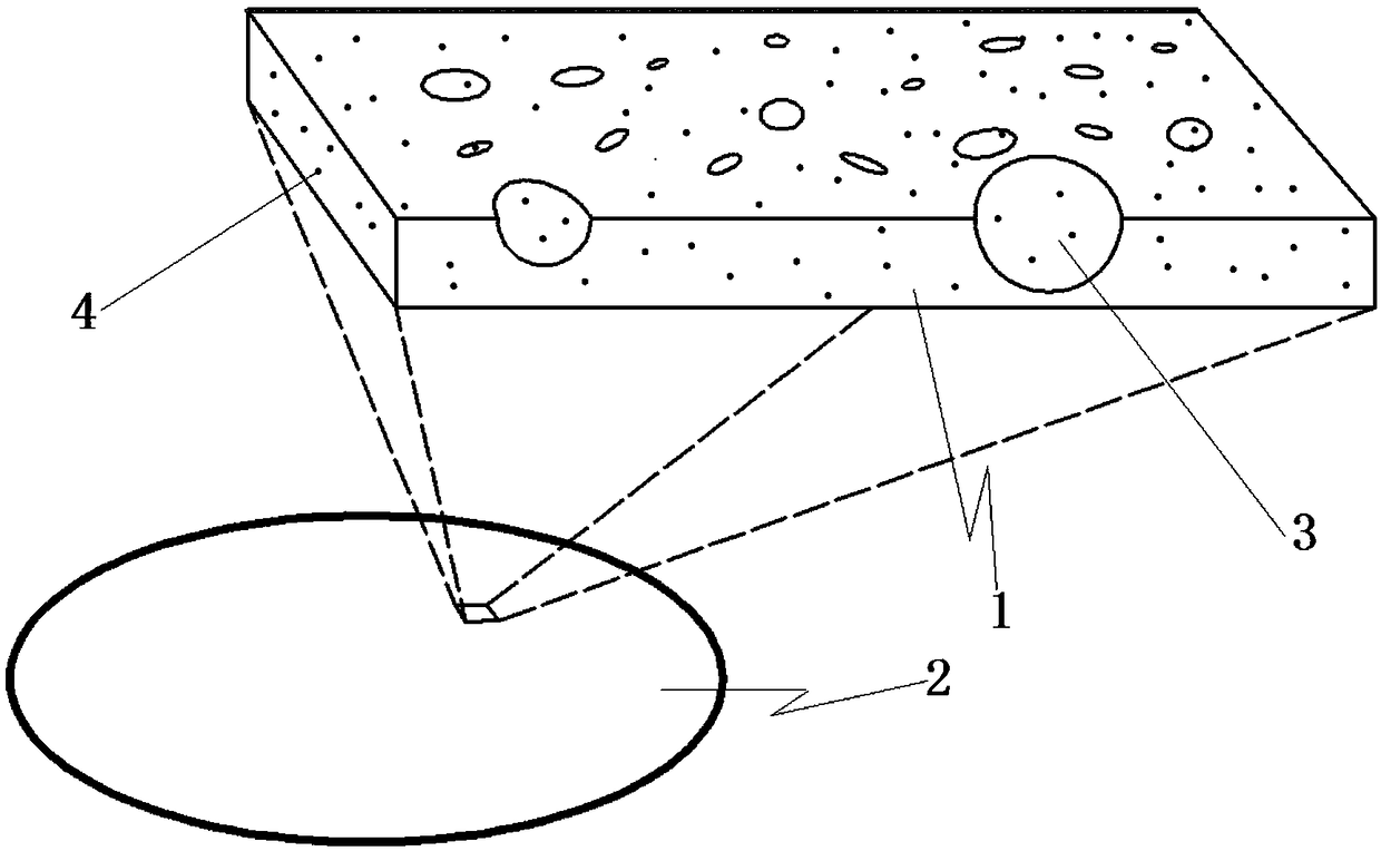
[0035] Such as figure 1 As shown, a perovskite patterned membrane realized by phase separation method, the membrane body is attached to the glass substrate at the macroscopic level, and the perovskite quantum dots are dispersed inside the membrane body at the microscopic level, and the patterned micropores are inlaid and buried. in the diaphragm body. The diaphragm body is a thin film made of high molecular polymer.

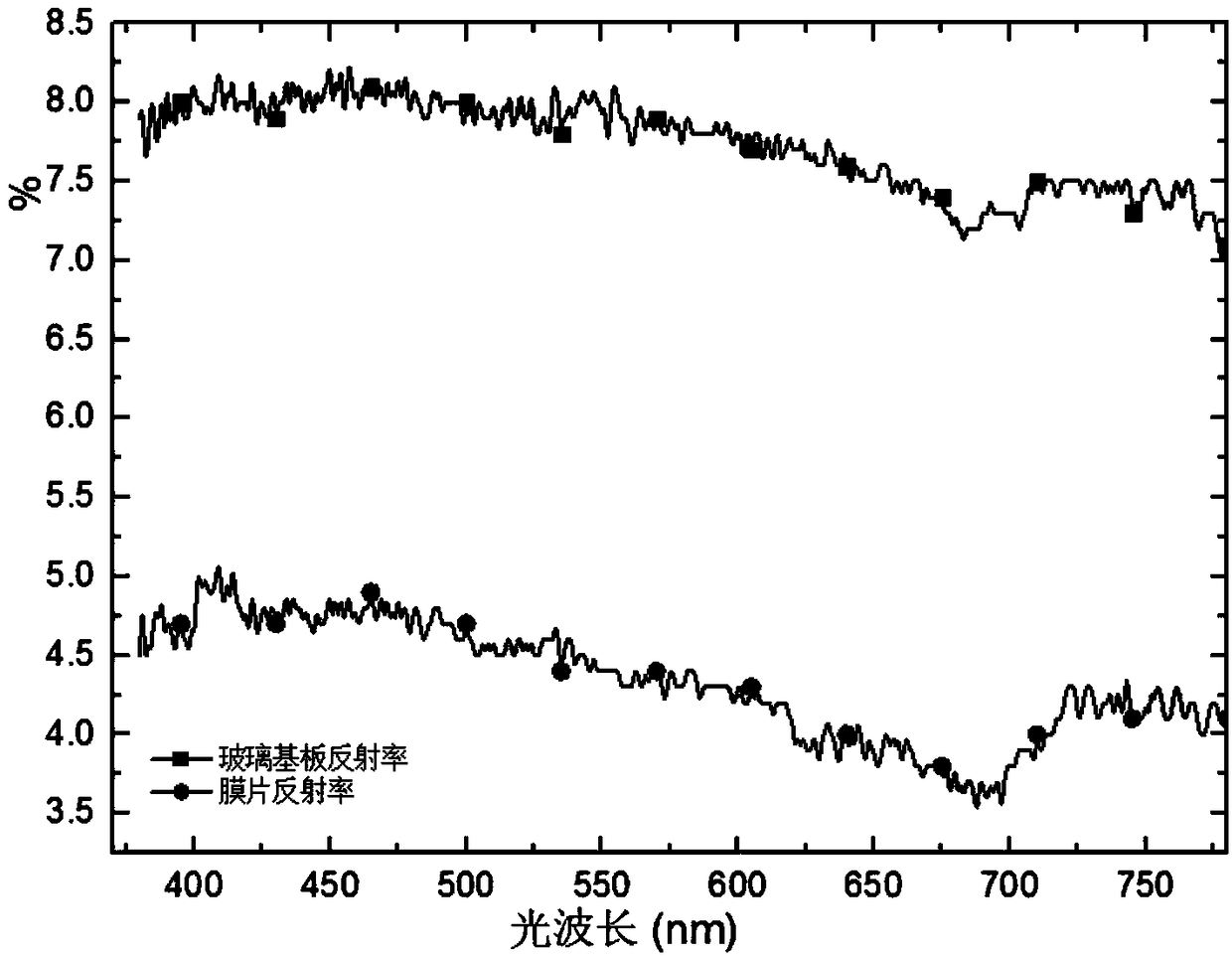
[0036] image 3 Measured by RF-6000 fluorescence spectrophotometer. Figure 4 Photographed by SEM electron microscope S3700 with a magnification of 9000 times.

[0037] A perovskite patterned diaphragm realized by phase separation method, comprising: a diaphragm body, patterned micropores are etched on the diaphragm body, perovskite quantum dots are dispersed inside the diaphragm body; the diaphragm body is polymer Films made of polymers. ...


PUM


Abstract

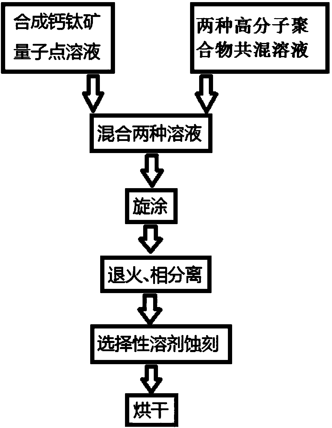
The invention relates to a perovskite patterned diaphragm obtained by a phase separation means. The perovskite patterned diaphragm comprises a diaphragm body. Patterned micropores are etched in the diaphragm body. Perovskite quantum dots are dispersed in the diaphragm body. The diaphragm body is a thin film made of high-molecular polymers. The diaphragm body is attached to a glass substrate. The invention further relates to a manufacturing method of the perovskite patterned diaphragm obtained by the phase separation means. The perovskite quantum dots are added to the patterned diaphragm obtained by the phase separation means, the advantages of the perovskite quantum dots of wide absorption peaks, narrow emission peaks, extremely high fluorescent efficiency and the like are combined with the effects of the patterned diaphragm of reducing reflection and increasing transmission by a gradient refraction index film, the effect of enhancing luminance is realized, excellent scattering performance is achieved, and the problems of dazzling, light spots and the like caused by too strong LED orientation are solved. The invention belongs to the technical field of packaging and manufacturing ofLED light-emitting materials.

Description

technical field [0001] The invention relates to the technical field of encapsulation and manufacturing of LED luminescent materials, in particular to a perovskite patterned diaphragm realized by phase separation means and a manufacturing method thereof. Background technique [0002] Quantum dots (Quantum Dots), as a light-emitting material with a particle size of nanometer, have attracted much attention because of their advantages such as wide absorption peaks, narrow emission peaks, and high fluorescence efficiency. The advantages of quantum dots based on perovskite structures are particularly prominent. As far as quantum dots are packaged with polymers to form quantum dot films, and then for optical applications, quantum dot films, as an optical film, have attracted much attention in the field of LED packaging, such as LCD backlight modules and remote fluorescent films for LED lamps. film etc. The application of quantum dot film can significantly improve the color saturat...

Claims


Application Information

Patent Timeline
Patent Type & Authority Applications(China)
IPC IPC(8): H01L33/58B82Y30/00
CPCH01L33/58B82Y30/00H01L2933/0058
Inventor 于桂栋李宗涛汤勇杜学威冯思洋姚侠楠
Owner SOUTH CHINA UNIV OF TECH
Learn More