
Large-power MBUS main controller circuit

A main controller, high-power technology, applied in the fields of instruments, electrical components, electrical digital data processing, etc., can solve the problem of reduced communication performance and product stability, low load capacity of the host bus remote power supply, difficult on-site maintenance and installation, etc. problems, to achieve the effect of improving the bus remote power supply driving capability, improving the effectiveness of communication, and enhancing the robustness of the signal

Pending Publication Date: 2018-06-29
RUINA INTELLIGENT EQUIP CO LTD
View PDF0 Cites 3 Cited by
  • Summary
  • Abstract
  • Description
  • Claims
  • Application Information

AI Technical Summary

Problems solved by technology

[0002] MBUS is a bus protocol specially designed for remote data transmission of heat meters. It is an important technology for the digitization of data transmission of measuring instruments. It has been widely used in passive contacts such as water, electricity, gas, heat meters and other data collection occasions. , the current existing MBUS host, the remote power supply of the host bus has low load capacity, poor driving load capacity, and poor adaptability of on-site products, which makes on-site maintenance and installation very difficult. At the same time, the existing MBUS host circuit has multiple loads. The sampling resistor in the receiving part of the host is hot and hot, and the long-term heating and hot state can easily cause the resistor to burn out, reduce the service life of the resistor, and reduce the communication performance and product stability.

Method used


Image

  • Large-power MBUS main controller circuit
  • Large-power MBUS main controller circuit
  • Large-power MBUS main controller circuit

Examples


Embodiment Construction

[0020] The high-power MBUS main controller circuit provided by the present invention will be further described in detail below in conjunction with the overall drawings and specific embodiments.

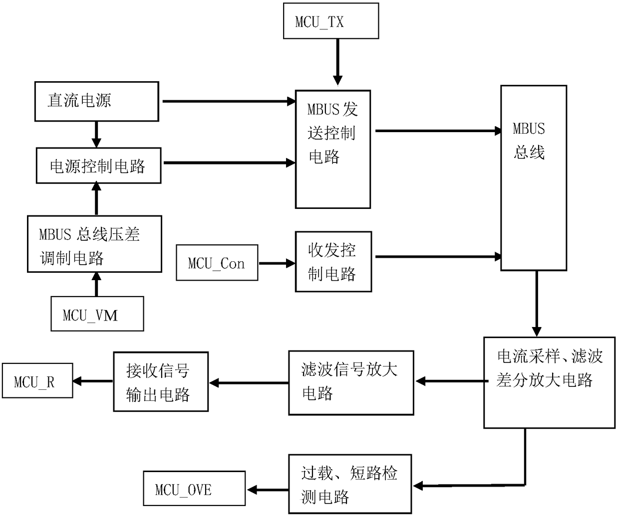
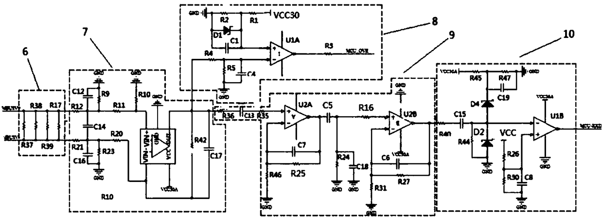
[0021] Such as figure 1 As shown, the high-power MBUS master controller circuit includes a host sending circuit and a host receiving circuit, and the host sending circuit includes a DC power supply 1, a sending control circuit 2 for receiving signals sent by the host, a transceiver control circuit 3, and a power supply control circuit 4 And the voltage modulation circuit 5 that regulates the power supply control circuit, the host receiving circuit includes a sampling resistor 6, a pre-stage filter differential amplifier circuit 7 connected to the sampling resistor, a signal output circuit 10, a filter amplifier circuit 9 and a current detection circuit 8 .

[0022] Such as figure 2 As shown, the DC power supply 1 includes a high-voltage rail power supply and a filter circuit. The fil...


PUM


Abstract

The invention provides a large-power MBUS main controller circuit which comprises a host computer sending circuit and a host computer receiving circuit; the host computer sending circuit comprises a direct-current power supply and a sending control circuit; the host computer receiving circuit comprises a sampling resistor, a pre-stage filter differential amplifier circuit and a signal output circuit; the pre-stage filter differential amplifier circuit comprises a pre-stage filter circuit and a differential amplifier circuit; the differential amplifier circuit comprises a computing amplifier; the pre-stage filter circuit comprises a first filter circuit and a second filter circuit; and the first filter circuit and the second filter circuit are output to the computing amplifier respectivelyand provide voltage output differential amplification signals through the computing amplifier. By adopting the large-power MBUS main controller circuit provided by the invention, the circuit design isconcise, the low-resistance value sampling resistor and the high-precision differential amplifier circuit are adopted to inhibit interference of a common mode signal and improve the stability of receiving the signal, and the slave node loading amount is increased.

Description

technical field [0001] The invention belongs to the technical field of control circuits, and in particular relates to a high-power MBUS main controller circuit. Background technique [0002] MBUS is a bus protocol specially designed for remote data transmission of heat meters. It is an important technology for the digitization of data transmission of measuring instruments. It has been widely used in passive contacts such as water, electricity, gas, heat meters and other data collection occasions. , the current existing MBUS host, the remote power supply of the host bus has low load capacity, poor driving load capacity, and poor adaptability of on-site products, which makes on-site maintenance and installation very difficult. At the same time, the existing MBUS host circuit has multiple loads. The sampling resistor in the receiving part of the host is hot and hot. Long-term heating and hot state can easily cause the resistor to burn out, reduce the service life of the resisto...

Claims


Application Information

Patent Timeline
Patent Type & Authority Applications(China)
IPC IPC(8): G08C19/00H04L12/40G06F13/42
CPCH04L12/40013H04L12/40019G06F13/42G08C19/00
Inventor 吕金叶陈家培王智王兆杰苏贤新
Owner RUINA INTELLIGENT EQUIP CO LTD
Learn More