
Time sequence control method and system for chemiluminescence immunoassay device

A chemiluminescent immunoassay and timing control technology, which is applied in the fields of life sciences and clinical diagnostic instruments, can solve problems such as timing conflicts, instrument throughput decline, and no timing control scheme for fully automatic chemiluminescence immunoassay analyzers, so as to avoid cycles The effect of conflict

Active Publication Date: 2018-06-29
CHONGQING CAPITALBIO NEW VIEW DIAGNOSTIC TECH CO LTD
View PDF10 Cites 23 Cited by
  • Summary
  • Abstract
  • Description
  • Claims
  • Application Information

AI Technical Summary

Problems solved by technology

This patent proposes a method of controlling the operation according to a fixed time beat, but only involves the control method of the incubation unit (i.e. the above 4 steps), and does not propose an overall timing control scheme for the fully automatic chemiluminescence immunoassay analyzer, and there are still many problems. big room for improvement
[0006] At the same time, the mechanical structure and timing control method of the existing orbital chemiluminescence immunoassay analyzer limit each module to complete a part of the action in each cycle, resulting in a decrease in the throughput of the instrument. It is difficult to guarantee the accuracy of the reaction time of each test, and there is a phenomenon of over-period
There are also resource occupation conflicts and cycle conflicts between a single reaction plate and the mixing structure, and the actions associated with the reaction plate include adding reagents, adding samples, adding magnetic beads, mixing and taking tubes by the feeding arm, feeding tubes by the feeding arm, and pipetting arm There is also a problem of timing conflicts in the series of actions such as taking the tube to the cleaning tray, and the transfer arm takes the tube from the cleaning tray and puts it back into the reaction tray.

Method used


Image

  • Time sequence control method and system for chemiluminescence immunoassay device
  • Time sequence control method and system for chemiluminescence immunoassay device
  • Time sequence control method and system for chemiluminescence immunoassay device

Examples


Embodiment Construction

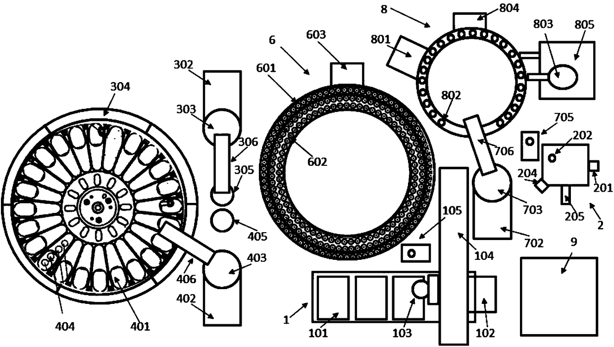
[0094] The technical solution of the present invention will be further described in detail below in conjunction with the accompanying drawings, but the protection scope of the present invention is not limited to the following description.

[0095] like figure 1 As shown, a timing control system for a chemiluminescence immunoassay analyzer includes a tube inlet module 1, a detection module 2, a sample module 3, a reagent module 4, a reaction tray module 6, a pipette module 7, a cleaning tray module 8 and a liquid road control module 9;

[0096] Wherein, the tube feeding module 1 includes a test tube rack, a tube feeding rack motor 102, a gripper 103, a tube feeding arm motor, a tube feeding arm guide rail 104, and a tube feeding mixing mechanism 105;

[0097] The detection module 2 includes a detection disk rotation motor 201, a detection disk hole 202, a detection disk mixing mechanism, a detection disk discarding mechanism 204, a PMT reader 205 and a substrate pump;

[0098...


PUM


Abstract

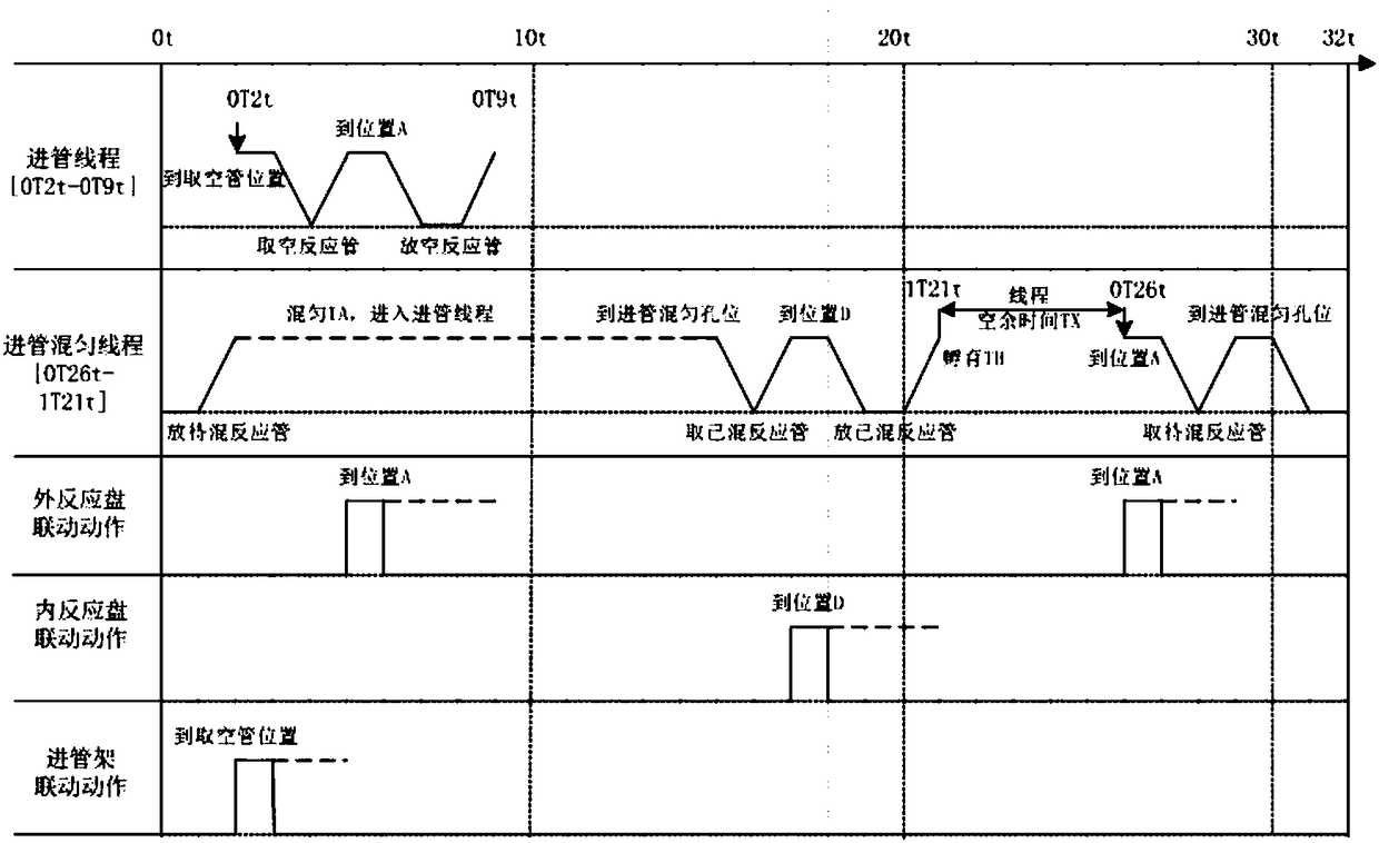
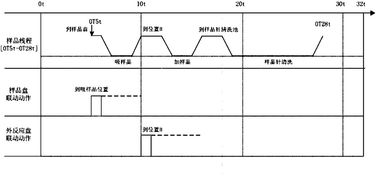
The invention discloses time sequence control method and system for a chemiluminescence immunoassay device. The system includes an input pipe module, a detection module, a sample module, a reagent module, a reaction plate module, a transfer pipe module, a cleaning disk module, and a liquid path control module. The control method includes flow line control to the units in the device according to time stamps and timing triggering, wherein a time sequence control part includes several key threads, which are completed in parallel in different zones simultaneously. In the method, actions of the device within 16 sec are defined as a time sequence period T, each 0.5 s defined as a timer t. The method, via reasonable hardware system arrangement in the CLIA device and systemic and complete time sequence control method design on the hardware layer, functional demands such as parallel control, seamless connection and abnormity treatment among different executing mechanisms in a bottom layer are achieved. The method achieves accurate control in a uniform period according to optimum time sequence flow, thus increasing test speed.

Description

technical field [0001] The invention belongs to the technical field of life sciences and clinical diagnostic instruments, in particular to a timing control method and system for a chemiluminescence immunoassay analyzer. Background technique [0002] In vitro diagnostic analysis instruments for body fluids, such as automatic biochemical and immune analyzers, blood cell analyzers, and flow cytometry analyzers, often encounter a large number of samples in the daily application of clinical users, such as infectious diseases, thyroid function, For testing items such as sex hormones, prenatal and postnatal care, and tumor standard substances, the average daily detection volume of a single instrument can reach hundreds of tubes of samples. For clinical users, it is an important core highlight of the instrument to improve the automation and intelligence of the instrument and reduce the time occupation of the operator. How to improve the detection speed of the instrument (usually ar...

Claims


Application Information

Patent Timeline
IPC IPC(8): G01N35/00
CPCG01N35/0092
Inventor 王智囊程振张兴鹏张冠斌高云
Owner CHONGQING CAPITALBIO NEW VIEW DIAGNOSTIC TECH CO LTD
Learn More