Damping device and gas injector with a damping device

A gas injector and vibration damping device technology, which is applied in the direction of shock absorbers, friction shock absorbers, solid shock absorbers, etc., can solve the problems of limited vibration damping effect, and achieve the effect of compact storage space, simple and robust structure

Active Publication Date: 2018-06-29
ROBERT BOSCH GMBH
View PDF11 Cites 0 Cited by
  • Summary
  • Abstract
  • Description
  • Claims
  • Application Information

AI Technical Summary

Problems solved by technology

However, it should be taken into account that the known damping elements or damping devices, although they also work without the use of a medium, have a damping effect that is limited to the range of the travel of the movably arranged element. The area in which the damping element comes into active connection with its counter element

Method used


Image

  • Damping device and gas injector with a damping device
  • Damping device and gas injector with a damping device

Examples


Embodiment Construction

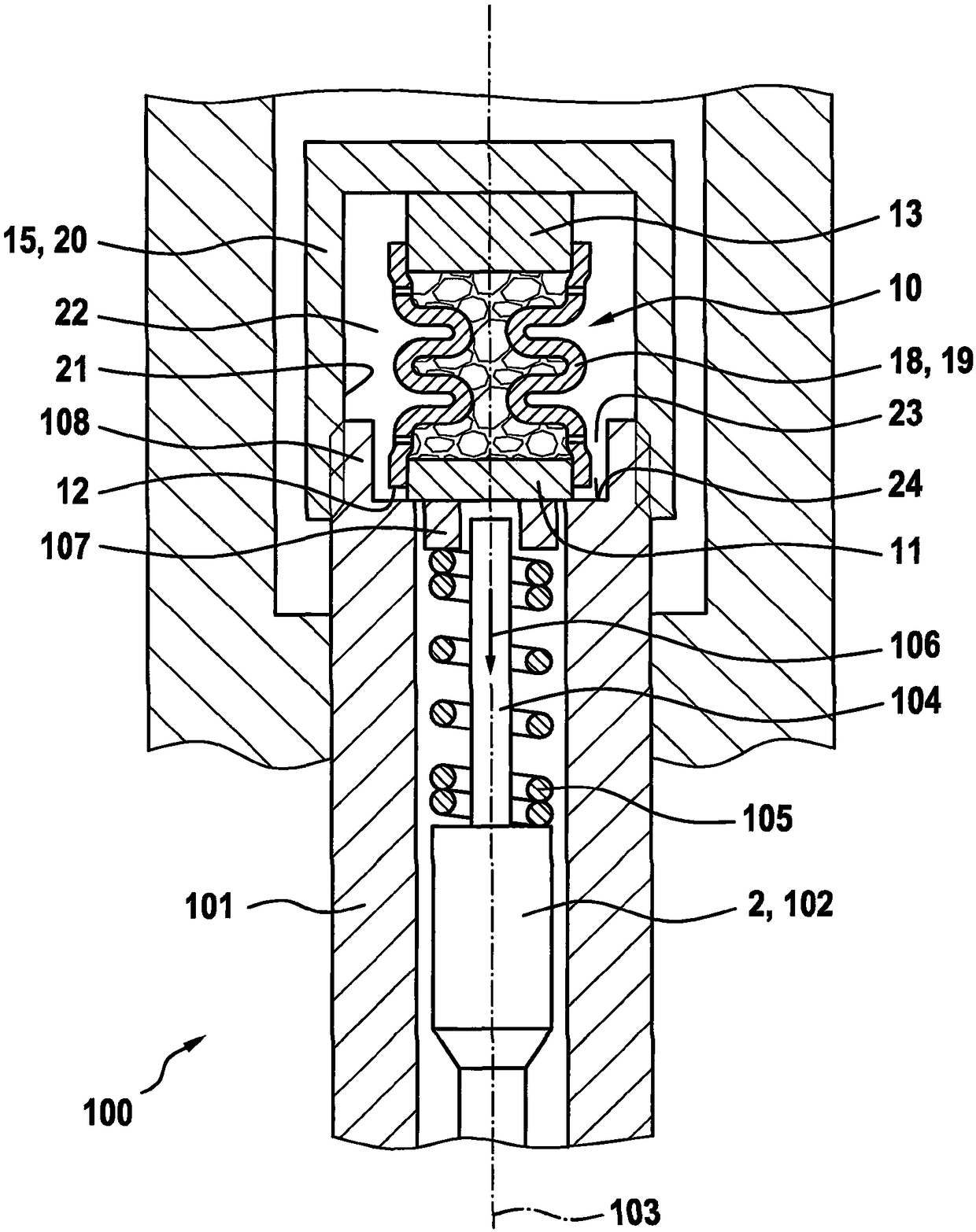
[0022] exist figure 1 The middle area shows a gas injector 100 , such as is provided, in particular in motor vehicles, for at least indirectly injecting gas into a combustion chamber of an internal combustion engine. The gas injector 100 has an injector housing 101 , in which a gas needle 102 is arranged movably in a bore along a longitudinal axis 103 as a movable element 2 . The gas needle 102 is connected at one end to a piston rod 104 which is radially surrounded by a spring element 105 , wherein the spring element 105 is designed as a compression spring and exerts a force acting on the gas needle 102 in the direction of the arrow 106 . . The end side of the spring element 105 facing away from the gas needle 102 rests axially on the damper 10 below the center position of the adjusting washer 107 , the thickness of which can be used to adjust the spring element 105 to act on the gas needle 102 The size of the preload.

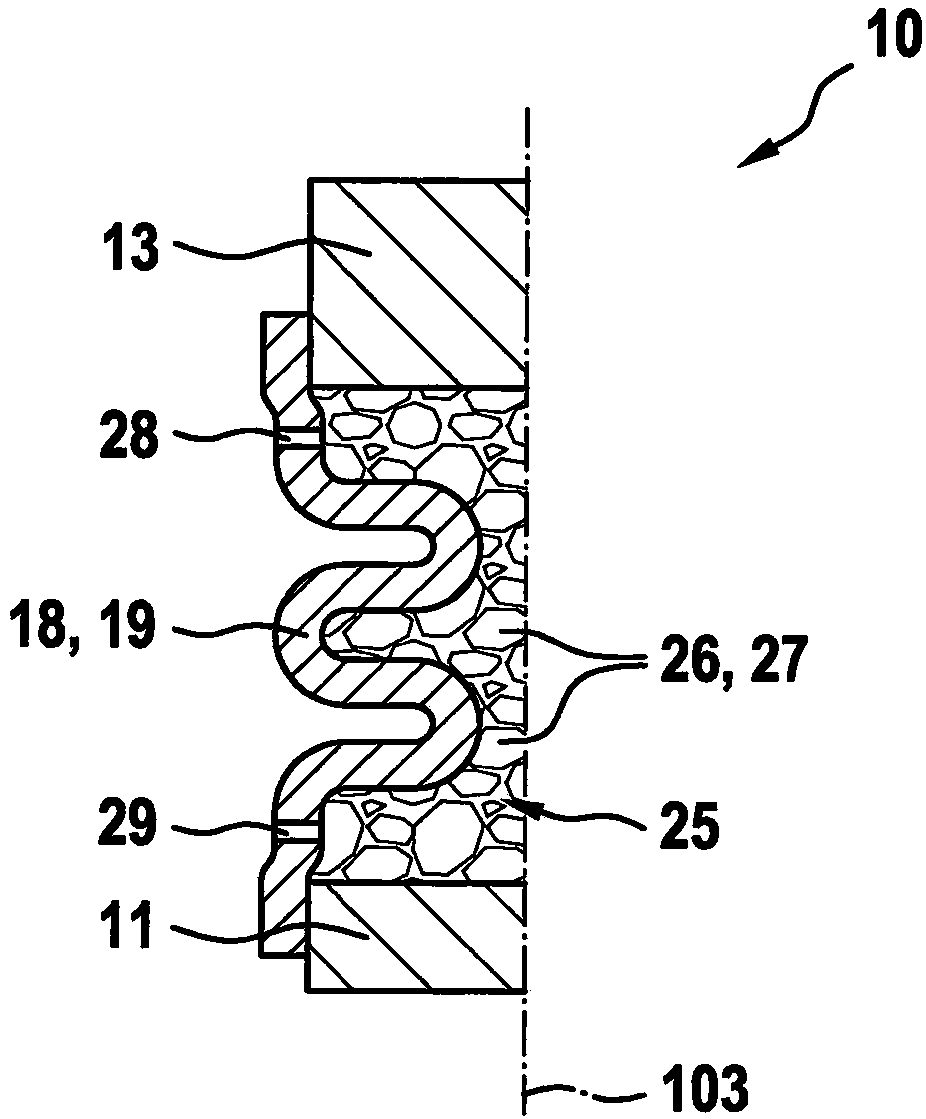
[0023] The damping device 10 has a plate-shaped firs...


PUM


Abstract

The invention relates to a damping device (10), in particular for a linearly movably arranged element (2, 102), having a storage space (25) for receiving a damping medium (26), wherein the damping medium (26) is designed, at least indirectly, with the Element (2, 102) cooperate to reduce its displacement energy at a displacement of the damping medium (26).

Description

technical field [0001] The invention relates to a vibration damping device. Furthermore, the invention relates to a gas injector with a damping device according to the invention. Background technique [0002] The damping device on which the invention is based is known from DE 10 2007 017 589 B3. The known damping device is characterized in that a fluid is used as a damping medium which is arranged in a storage space with a plurality of partial spaces. When the element to be damped moves, the element acts at least indirectly on the damping medium, so that the damping medium is pressed from the first subregion of the storage space into the second subregion of the storage space. Said compression of the damping medium has the effect that the kinetic energy of the movable element is reduced or at least partially absorbed. Such damping devices are used, for example, in the motor vehicle sector in the form of shock absorbers or the like. In order to prevent the liquid medium fr...

Claims


Application Information

Patent Timeline
IPC IPC(8): F16F9/30F16F9/32
CPCF16F9/303F16F9/3207F16F7/01F16F2230/105F02M61/20F02M21/0248F02M2200/306Y02T10/30
Inventor J·韦斯内尔M·卡茨
Owner ROBERT BOSCH GMBH
Why Eureka
Try Eureka