A beam-column hinged joint

A node and hinge technology, applied in the direction of architecture and building structure, can solve problems such as potential safety hazards, inconsistency of theoretical models, differences between the force of the structural system and calculation settings, etc., to achieve the effect of improving safety and eliminating potential safety hazards

Active Publication Date: 2020-08-04
STATE NUCLEAR ELECTRIC POWER PLANNING DESIGN & RES INST CO LTD
View PDF1 Cites 0 Cited by
  • Summary
  • Abstract
  • Description
  • Claims
  • Application Information

AI Technical Summary

Problems solved by technology

[0005] Although the hinge joints in the construction project can realize the connection between the steel beam and the steel column, but in this way, the steel beam cannot rotate around the axis parallel to the two flanges and perpendicular to the web, which is inconsistent with the theoretical model. There is a certain difference in the force of the system and the calculation setting, which has caused a safety hazard

Method used


Image

  • A beam-column hinged joint
  • A beam-column hinged joint
  • A beam-column hinged joint

Examples


Embodiment Construction

[0074] In order to make the technical solutions and advantages of the present invention clearer, the embodiments of the present invention will be further described in detail below in conjunction with the accompanying drawings.

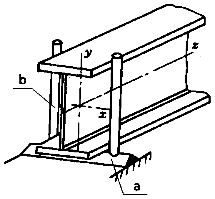
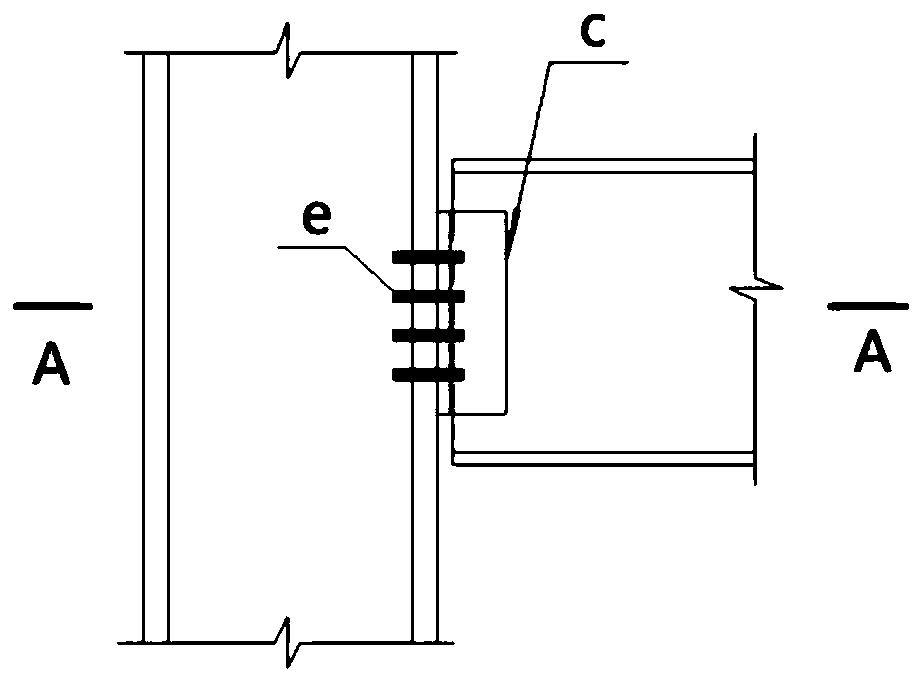
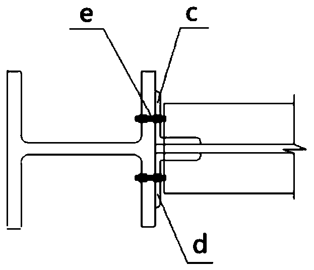
[0075] The embodiment of the present invention provides a beam-column hinged joint, its structural disassembly diagram is as follows Figure 4 As shown, the schematic diagram of its structure after installation is shown in Figure 5 As shown, it includes: a first fixing component 1 and a second fixing component 2 .

[0076] Wherein, the first fixing assembly 1 includes a first corner plate 101 and a first plate body 102, and the first corner plate 101 and the first plate body 102 are arranged near the first flange 301 or the second flange 303 of the steel beam 3 Both sides of the web 302, the side plate surface of the first angle plate 101 and the side end surface of the first plate body 102 are respectively connected with the steel column 4;

[0077...


PUM


Abstract

The invention discloses a beam column hinged joint, and belongs to the field of steel structures. the beam column hinged joint is fixed to a steel column through a first fixing assembly and a second fixing assembly. Due to the fact that a second angle plate and a second plate body are arranged on the two sides of a web, close to a steel beam, of a first flange or a second flange, and the second angle plate and the second plate body support a web of the steel beam, the steel beam can not achieve rotation with the direction parallel to the first flange, the second flange and the web as the axis.Due to the clamping and fixing of the second fixing assembly, and the hole diameters of a first through hole, a third through hole and a second through hole are all larger than the diameter of a screw of a first bolt, the steel beam can use the second fixing assembly as a supporting point to achieve the rotation with the direction parallel to the first flange and the second flange and perpendicular to the web plate as the axis when being exerted by external forces. The structure of the beam column hinged joint more accords with the structure of a hinged joint in an ideal state, the safety ofthe structure is improved, and the safety hazards on the structure are removed.

Description

technical field [0001] The invention relates to the field of steel structures, in particular to a beam-column hinge joint. Background technique [0002] Simply supported beam is a beam structure commonly used in engineering, and the steel beam is connected to the steel column through hinged nodes at both ends. The schematic diagram of the hinged joint under ideal conditions is as follows: figure 1 As shown, by setting a horizontal support seat a and two rods b on the surface of the steel column, one end of the steel beam can be erected on the support seat a and fixed by the rod body b. The steel beam can realize: (1) winding The axis is free to rotate along the direction parallel to the two flanges and perpendicular to the web, such as figure 1 (2) It cannot rotate freely around the axis parallel to the direction of the two flanges and the web, such as figure 1 in the z-axis. [0003] Schematic diagram of the joint joints commonly used in actual engineering, such as fi...

Claims


Application Information

Patent Timeline
Patent Type & Authority Patents(China)
IPC IPC(8): E04B1/24E04B1/58
CPCE04B1/2403E04B2001/2406E04B2001/2415E04B2001/2418
Inventor 陈世玺黄友强花秀峰张玉超王腾秦素娟张爱中罗春霞冯云霞李鸿维
Owner STATE NUCLEAR ELECTRIC POWER PLANNING DESIGN & RES INST CO LTD
Why Eureka
Try Eureka