


Quick Research
Generate reliable direction feasibility study reports for your R&D in just a few steps.

Technical Q&A
Discover and master advanced knowledge NOW. Basics, ideas, possibilities, all at once.

Find Solutions
As an expert in R&D theories, this can generate solutions to your technical problems instantly.

Evaluate Feasibility
Analyze your overall solution with one click, know your potential R&D risks in advance.

Monitor Landscape
Get weekly tech updates, stay abreast of the latest tech innovations and key insights.
Dust control unit for road construction
A technology of dust removal device and road construction, which is applied in the directions of road cleaning, use of liquid separation agent, separation of dispersed particles, etc., can solve the problems of poor dust removal effect and low work efficiency, and achieves stable rotation, not easy to shake and fall off, and high dust removal efficiency. Effect
- Summary
- Abstract
- Description
- Claims
- Application Information
AI Technical Summary
Problems solved by technology
Method used
Image

Examples
Embodiment 1
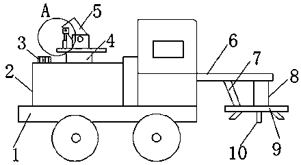
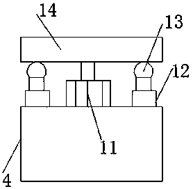
[0024] see Figure 1-6 As shown, a dust removal device for road construction includes a car body 1, a water tank 2, a spray cylinder 5 and a high-pressure nozzle 10, the top of the car body 1 is connected with a water tank 2, and the middle end of the top of the water tank 2 is connected with a support column 4, which supports The top of the column 4 is connected with a top plate 14, and several telescopic columns 12 are installed between the top plate 14 and the support column 4. The top of the telescopic column 12 is movably connected with balls 13, and the shock-absorbing spring 18 inside the telescopic column 12 pushes the balls 13 and the bottom of the top plate 14. Contact, when the first motor 11 drives the top plate 14 to rotate, the rolling friction between the ball and the top plate 14 does not affect the work of the top plate 14, and the telescopic column 12 supports the top plate 14 from the bottom, and the top sides of the top plate 14 are connected with side plate...
Embodiment 2
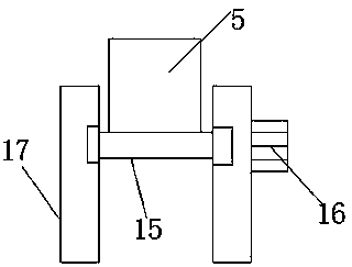
[0026] Additionally, according to Figure 1-6 As shown, the difference between it and the above embodiment is that a water pump 3 is installed on one side of the water tank 2, and the water pump 3 connects the nozzle 5 and the water pipe 7 through an internal pipeline, and the water pump 3 delivers the water inside the water tank 2 to the spray barrel 5 and the high pressure Inside the shower head 10, it is guaranteed that the spray barrel 5 and the high-pressure shower head 10 can spray high-pressure water during work. A first motor 11 is installed between the top plate 14 and the support column 4, and a second motor 16 is installed through the side plate 17 at one end of the rotating shaft 15. The first motor 11 drives the top plate 14 from the bottom to rotate in the horizontal direction, and the second motor 16 Drive the rotating shaft 15 and the spray tube 5 to rotate in the vertical direction, and the two motors work together to make the spray tube 5 change the direction...
PUM
 Abstract
Description
Claims
Application Information
 - R&D Engineer
- R&D Manager
- IP Professional
- Industry Leading Data Capabilities
- Powerful AI technology
- Patent DNA Extraction
Browse by: Latest US Patents, China's latest patents, Technical Efficacy Thesaurus, Application Domain, Technology Topic, Popular Technical Reports.
© 2024 PatSnap. All rights reserved.Legal|Privacy policy|Modern Slavery Act Transparency Statement|Sitemap|About US| Contact US: help@patsnap.com