
Forming method suitable for T-shaped and L-shaped composite material wall plates

A composite material and forming method technology, applied in the field of composite material forming, can solve the problems of relatively high mold pressure resistance and accuracy, poor temperature field uniformity, high mold cost and price, and achieve good internal quality and molding quality Good, the effect of less mold

Inactive Publication Date: 2018-06-29
AVIC COMPOSITES
View PDF3 Cites 6 Cited by
  • Summary
  • Abstract
  • Description
  • Claims
  • Application Information

AI Technical Summary

Problems solved by technology

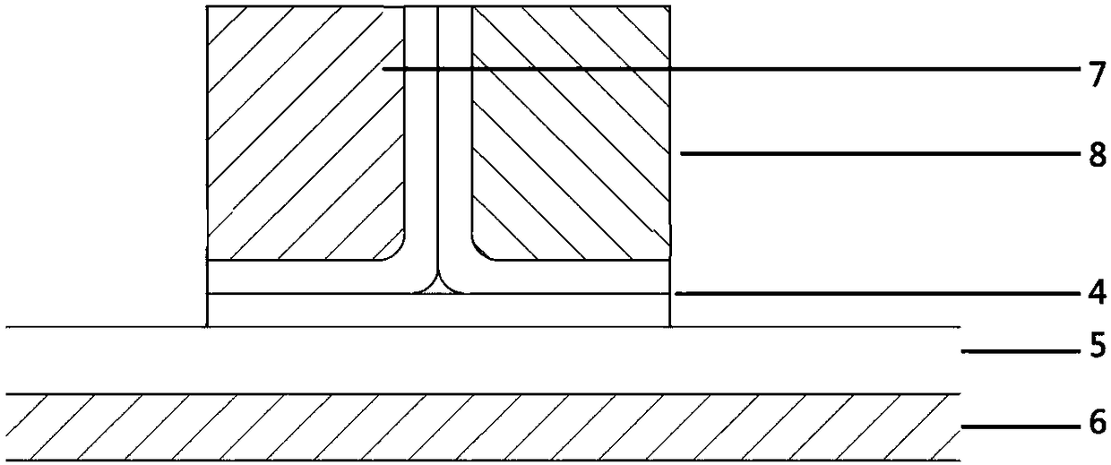
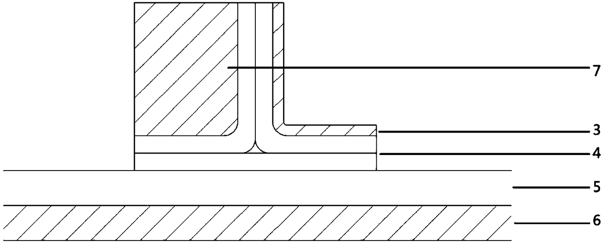
[0002] The traditional T-shaped and L-shaped composite wall panel forming process methods are more mature. There are A (hard mold and hard mold combined forming) and B (hard mold and soft mold combined forming). If the traditional method is used to prepare the wall panel, it will Bring a lot of difficulties in manufacturing, if use hard mold and hard mold to form (such as figure 1 as shown) or molded with soft mold and hard mold (such as figure 2 shown), then
[0003] 1. There is a perfect fit between the die and the die, and there will definitely be a fit gap, which will cause uneven pressure transmission and easily cause internal quality defects;
[0004] 2. Put too many molds in the vacuum bag, resulting in uneven heat transfer and poor uniformity of temperature field;
[0005] 3. The hard mold should be put into the tank together with the parts, which requires relatively high pressure resistance and accuracy of the mold, resulting in high mold cost and price;
[0006] 4. If the thickness of the skin changes greatly, or the shape of the skin changes greatly, if the traditional molding method is used, there will be assembly gaps and poor molding quality

Method used


Image

  • Forming method suitable for T-shaped and L-shaped composite material wall plates
  • Forming method suitable for T-shaped and L-shaped composite material wall plates
  • Forming method suitable for T-shaped and L-shaped composite material wall plates

Examples


Embodiment Construction

[0030] The present invention is described in detail in conjunction with accompanying drawing:

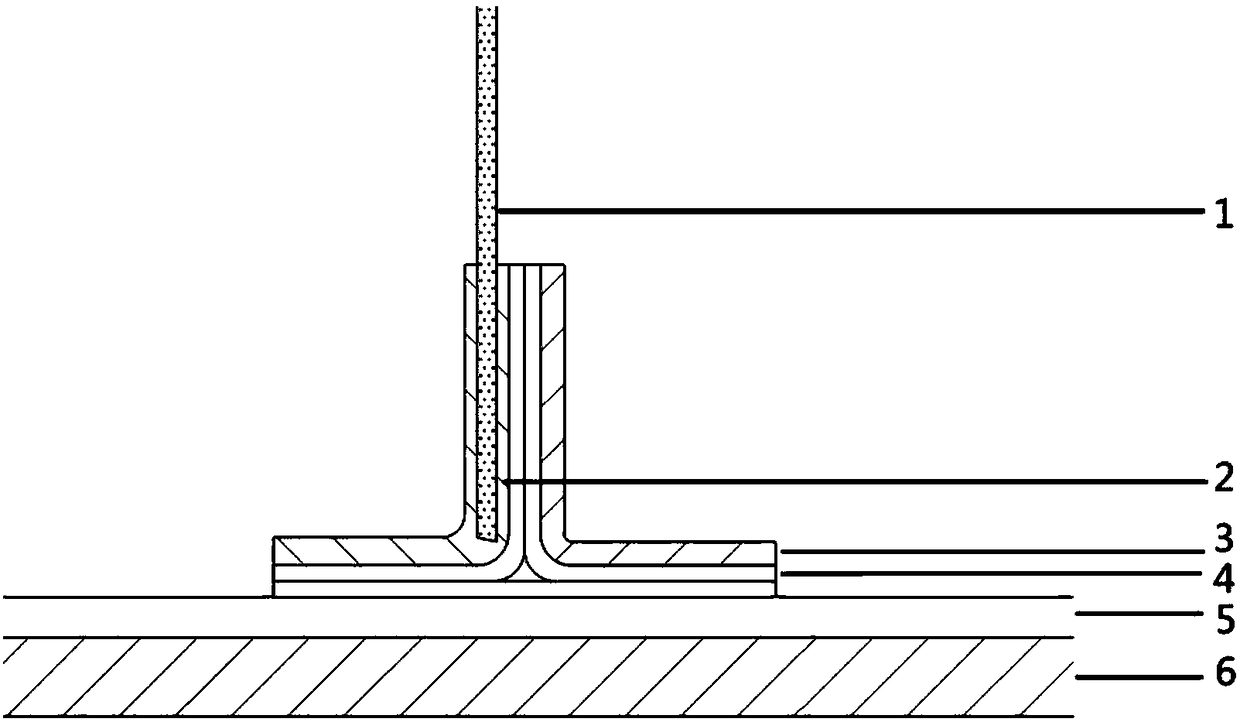
[0031] 1). Prepare a T-shaped reinforced wall panel, install the positioning plate 1 on the skin mold 6, the thickness of the positioning plate 1 is 3mm, and the installation position of the positioning plate 1 is outside the skin margin line and placed on the rib 4 vertical one side of the tendon;

[0032] 2). According to the shape of the reinforcing rib 4, the soft film forming mold is prepared. The reinforcing rib has a soft film forming mold 10 and a soft film forming mold 11. Consistent shape on both sides;

[0033] 3) Remove the positioning plate 1 on the skin mold 6, and wrap a layer of rubber on both sides of the positioning plate 1. The rubber starts to wrap from the position where the positioning plate 1 is at the same height as the vertical rib of the reinforcing rib, and the length of the wrapping is the same as that of the reinforcing rib 4 The profiles on the left s...


PUM


Abstract

The invention belongs to the technical field of forming of composite materials, and relates to a forming method suitable for T-shaped and L-shaped composite material wall plates. A forming mode combining a soft film positioning plate and a soft film is adopted, a fit clearance does not exist, pressure transmission is uniform, and the internal quality of formed wall plates is good. There are only afew molds in a vacuum bag, heat transferring is uniform, and the uniformity of a temperature field is good. The number of molds entering a tank is small, a soft film forming mold is low in precisionand does not need to enter the tank, and the overall mold cost is low. The assembling clearance is small, the forming quality is good, and the forming method is suitable for wall plates with large skin thickness change or large skin shape change. By means of the forming method suitable for T-shaped and L-shaped composite material wall plates, the internal quality of composite material wall platesformed through the method is high, studs are high in position precision, and the forming method is particularly suitable for forming wall plates with complex surfaces and many variable-thickness areas, and lays a certain technical foundation for development of composite materials.

Description

technical field [0001] The invention belongs to the technical field of composite material molding, and relates to a molding method suitable for T-shaped and L-shaped composite material wall panels. Background technique [0002] The traditional T-shaped and L-shaped composite wall panel forming process methods are more mature. There are A (hard mold and hard mold combined forming) and B (hard mold and soft mold combined forming). If the traditional method is used to prepare the wall panel, it will Bring a lot of difficulties in manufacturing, if use hard mold and hard mold to form (such as figure 1 as shown) or molded with soft mold and hard mold (such as figure 2 shown), then [0003] 1. There is a perfect fit between the die and the die, and there will definitely be a fit gap, which will cause uneven pressure transmission and easily cause internal quality defects; [0004] 2. Put too many molds in the vacuum bag, resulting in uneven heat transfer and poor uniformity of ...

Claims


Application Information

Patent Timeline
Patent Type & Authority Applications(China)
IPC IPC(8): B29C70/30B29C70/54
CPCB29C70/30B29C70/54
Inventor 姚锋毕红艳
Owner AVIC COMPOSITES
Learn More