
Flange plate grinding device

A technology for sharpening knives and racks, used in grinding/polishing safety devices, grinding machines, grinding workpiece supports, etc., can solve problems such as inability to change the angle, inability to perform grinding, etc., to achieve easy processing, reduce processing costs, and environmentally friendly processing cost effect

Inactive Publication Date: 2018-06-29
重庆市乐珐机电有限责任公司
View PDF1 Cites 3 Cited by
  • Summary
  • Abstract
  • Description
  • Claims
  • Application Information

AI Technical Summary

Problems solved by technology

[0004] Although the above-mentioned patent can also grind the side of the flange while grinding the end face of the flange, because the position of the mounting plate is fixed, it can only grind the cylindrical flange to remove the burrs on the side. When grinding a tapered flange, the angle cannot be changed with the taper of the flange, and grinding cannot be performed

Method used


Image

  • Flange plate grinding device
  • Flange plate grinding device

Examples


Embodiment Construction

[0019] Further detailed explanation through specific implementation mode below:

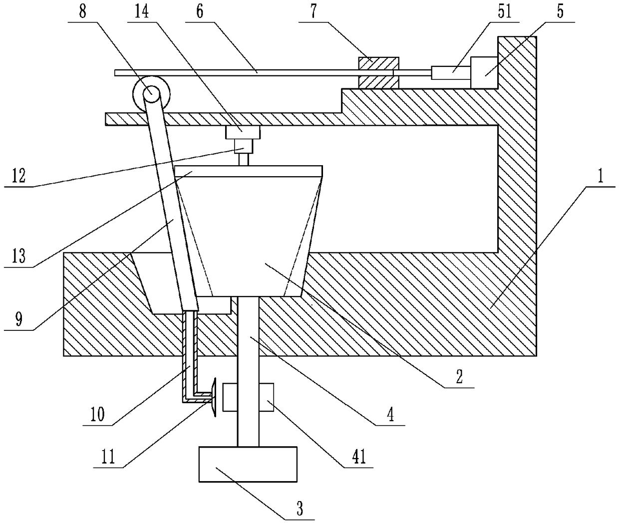
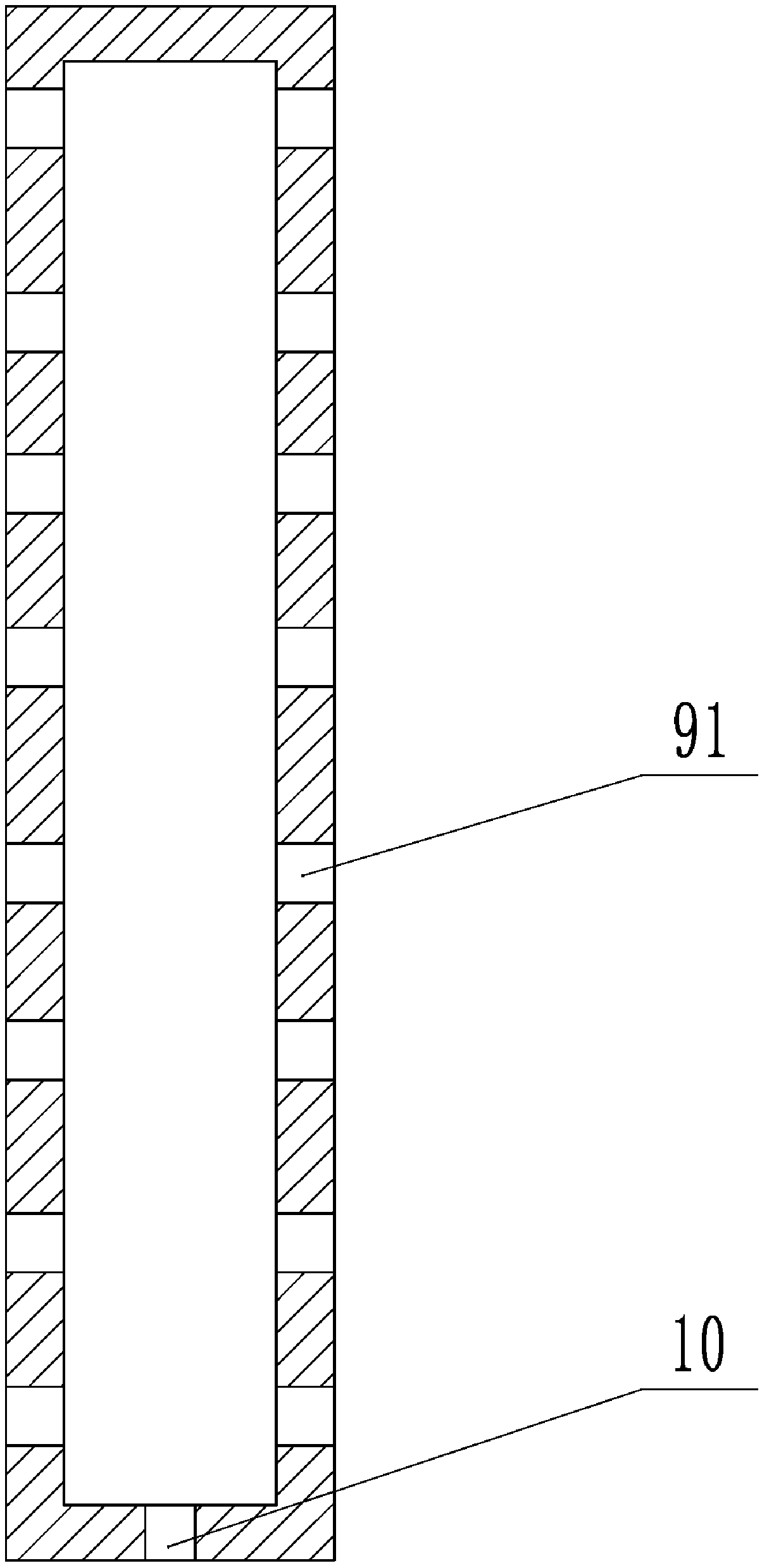
[0020] The reference signs in the drawings of the description include: frame 1, flange plate 2, motor 3, rotating shaft 4, fan blade 41, first cylinder 5, first output rod 51, rack 6, fixed block 7, gear 8 , grinding knife 9, air hole 91, vent pipe 10, air collecting port 11, second cylinder 12, pressing plate 13, rotating block 14.

[0021] like figure 1 As shown, the flange grinding device includes a frame 1 and a grinding knife 9. There is a positioning notch for placing the flange 2 on the frame 1. There is a rotating shaft 4 inside the positioning notch. The rotating shaft 4 runs through the frame 1 and the rotating shaft 4 is connected with a motor 3, when the motor 3 is started, the rotating shaft 4 rotates with the motor 3 and then drives the flange 2 to rotate. The frame 1 is also rotatably connected with a rotating block 14, the second cylinder 12 is welded on the rotating block 14, t...


PUM


Abstract

The invention belongs to the field of grinding devices, and particularly relates to a flange plate grinding device. The flange plate grinding device comprises a machine frame and a grinding knife, wherein the machine frame is provided with a positioning spigot, a rotating shaft is arranged on the machine frame in a penetrating mode, one end of the rotating shaft is located in the positioning spigot, and the other end of the rotating shaft is connected with a motor; fan blades are further arranged on the rotating shaft, and an air collecting opening is formed in one side of one fan blade; a knife placing groove for allowing the grinding knife to rotate is further formed in one side of the positioning spigot, a cavity is formed in the grinding knife, and a vent pipe is arranged in the bottomof the knife placing groove and penetrates through the machine frame; one end of the vent pipe communicates with the cavity of the grinding knife, and the other end of the vent pipe communicates withthe air collecting opening; air holes are further formed in the grinding knife, a first air cylinder is further fixedly connected to the machine frame, and an output rod of the first air cylinder isfixedly connected with a rack; and a gear way is arranged on the machine frame, a gear is arranged between the rack and the gear way in a meshed mode, and the grinding knife is rigidly connected withthe gear. According to the scheme, the flange plate grinding device can be used for machining a flange plate with a taper, and is mostly used for machining the flange plate with the taper.

Description

technical field [0001] The invention belongs to the field of grinding devices, in particular to a flange grinding device. Background technique [0002] The tapered flange uses a tapered short neck to strengthen the flange ring, and the small end of the tapered neck is welded together with the cylindrical shell, which increases the rotational stiffness of the flange, thereby reducing the stress in the flange and improving the performance of the flange. The gasket sealing condition is more economical and effective than increasing the thickness or diameter of the flange ring, so it is mostly used in medium and high pressure occasions. The surface of the flange needs to be ground before it can be used. At present, the grinding machine is mainly a grinding wheel grinder, which fixes the flange on the workbench and then grinds it through a sharpener. This operation can only grind a part of the flange each time, that is, Either grind the inner ring or the outside of the flange, wh...

Claims


Application Information

Patent Timeline
Patent Type & Authority Applications(China)
IPC IPC(8): B24B5/14B24B41/06B24B55/02
CPCB24B5/14B24B41/06B24B55/02
Inventor 印承霜
Owner 重庆市乐珐机电有限责任公司
Learn More