
Automatic assembling jig for power supply, and test device thereof

A technology for assembling jigs and testing devices, applied in power supply testing, assembling machines, electrical components, etc., can solve problems such as low efficiency, high cost, and difficulty in ensuring the consistency of assembled products, and achieve the effect of avoiding damage

Active Publication Date: 2018-06-29
SHENZHEN XING GRAIN AUTOMATION CO LTD
View PDF5 Cites 1 Cited by
  • Summary
  • Abstract
  • Description
  • Claims
  • Application Information

AI Technical Summary

Problems solved by technology

The traditional power supply assembly and test lines are generally assembled by using pull wires, that is, multiple manual workstations are set on the pull wires. After the components of the power supply flow to each workstation on the pull wires, the assembly and test of the power supply are completed manually. Power supply assembly and testing methods are inefficient, and it is difficult to ensure the consistency of assembled products; with the continuous increase in labor costs, the cost of traditional manual assembly and testing of power supplies is getting higher and higher. Automatic power supply assembly and testing is the future development trend

Method used


Image

  • Automatic assembling jig for power supply, and test device thereof
  • Automatic assembling jig for power supply, and test device thereof
  • Automatic assembling jig for power supply, and test device thereof

Examples


Embodiment Construction

[0037] The present invention will be further described below in conjunction with the accompanying drawings:

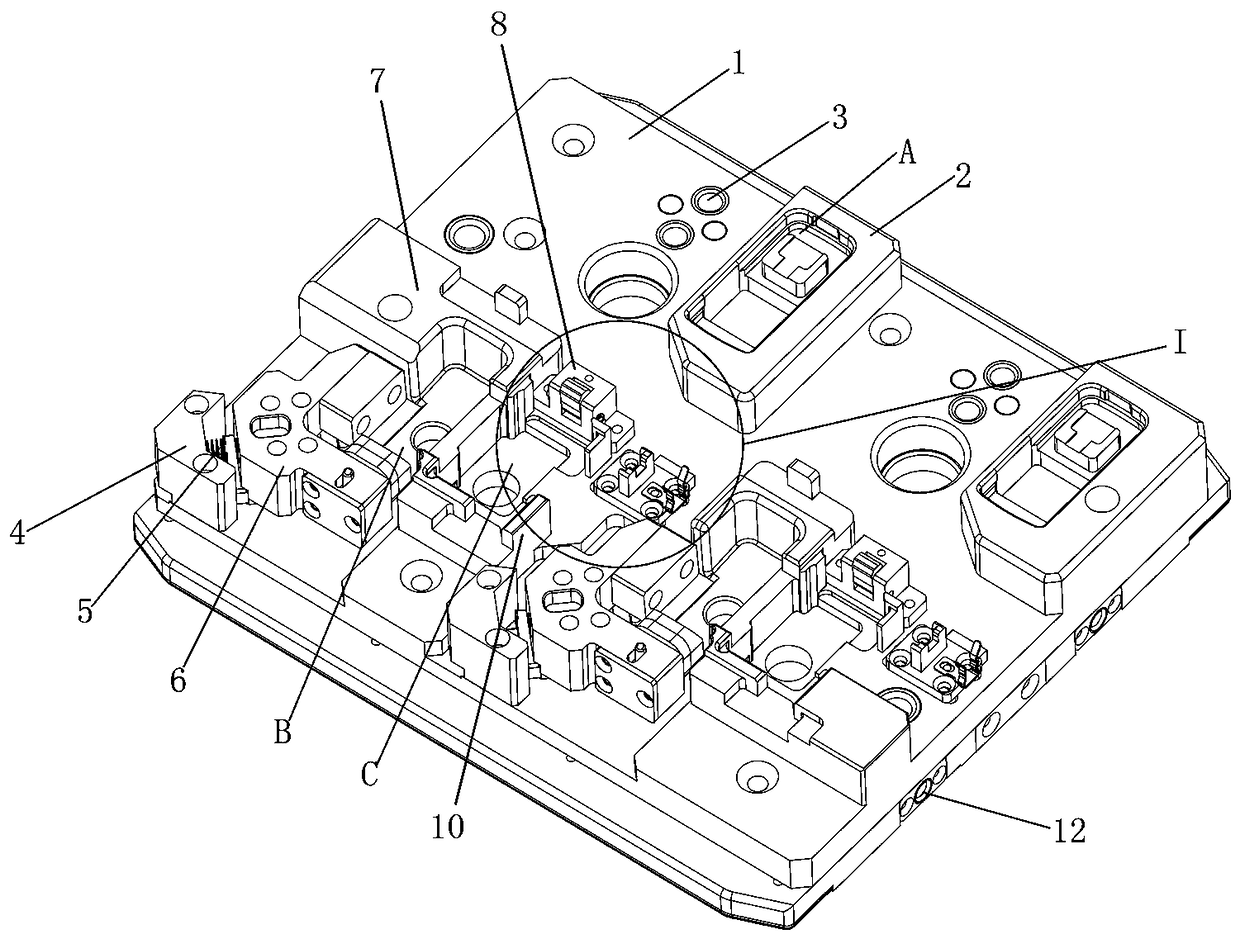
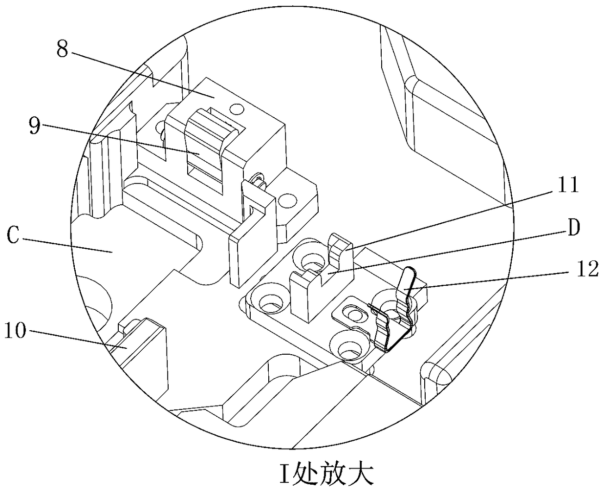
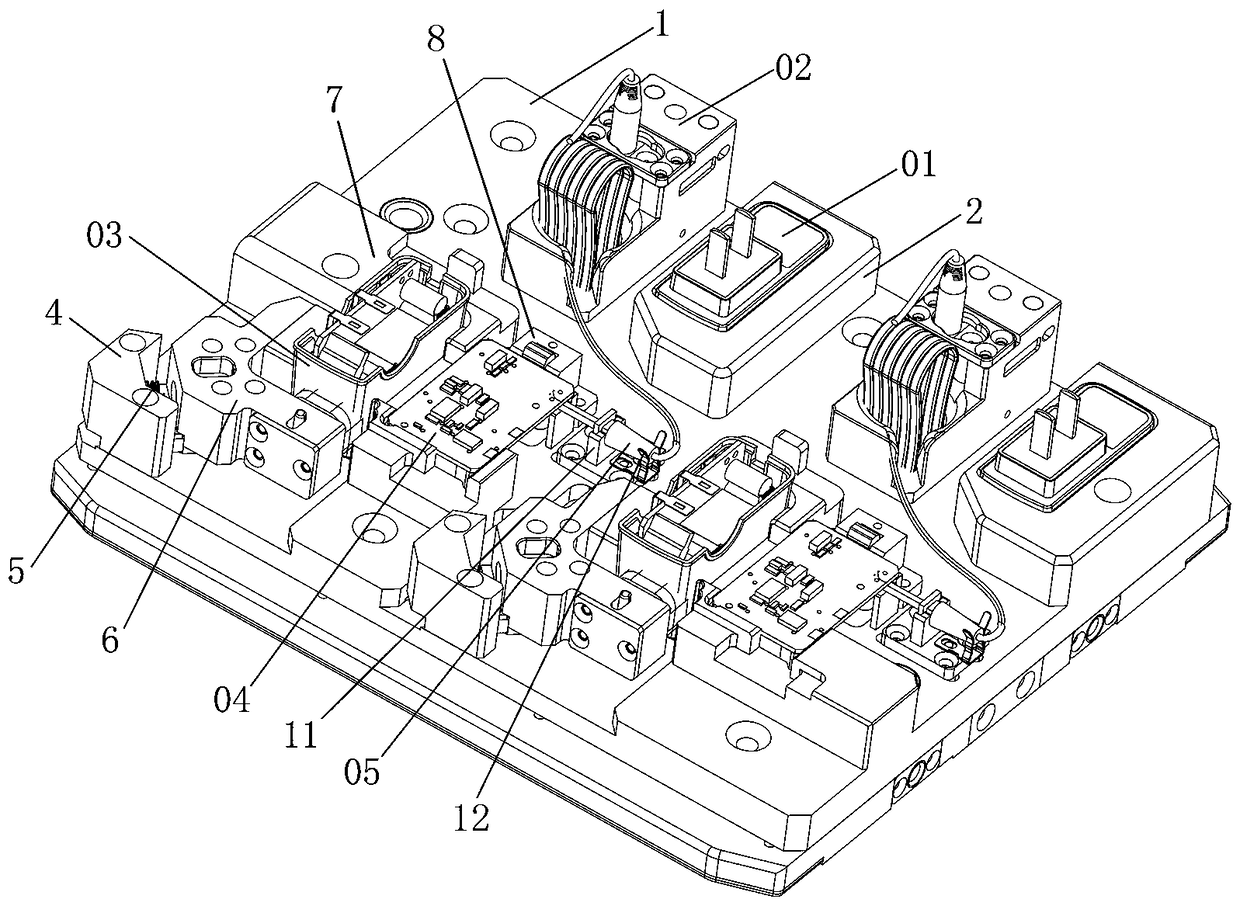
[0038] Such as Figure 1 to Figure 6 As shown, the technical solution adopted by the present invention is as follows: a power supply automation assembly jig, including a jig seat 1, a clamping assembly and a test socket 12, wherein the jig seat 1 is a plate-shaped structure; the clamping assembly At least two sets are included. Each clamping assembly is arranged on the fixture base 1 at intervals along the left and right direction to clamp at least two power supply components; the clamping assembly includes an upper cover base 2, a socket 3, a lower cover clamping part, and a PCB Board clamping components and DC cord clamping components; the upper cover seat 2 is arranged near the rear side of the fixture seat 1, and the upper cover seat 2 is embedded with the upper cover 01; the above-mentioned socket 3 is arranged in the upper cover seat 2 On the left side, the test soc...


PUM


Abstract

The invention discloses an automatic assembling jig for a power supply, and a test device thereof. The jig comprises a jig base, clamping assemblies and test jacks, wherein the jig base is of a platystructure; at least two sets of clamping assemblies are arranged; each clamping assembly comprises an upper cover base, a jack, a lower cover clamping part, a PCB (Printed Circuit Board) clamping partand a DC (Direct Current) wire clamping part; an upper cover is embedded into each upper cover base; a test base is detachably arranged on each jack; a lower cover is elastically arranged in each lower cover clamping part; each PCB clamping part is arranged on the right side of each lower cover clamping part; a PCB is elastically embedded onto each PCB clamping part; a DC wire is detachably embedded onto each DC wire clamping part; the test jacks are arranged on two sides of the jig base; and a test mechanism located above the jig is inserted into the test jacks, and the jig base is lifted upwards, so that the test bases on the jig base are electrically conducted with the test mechanism. The automatic assembling jig for the power supply provided by the invention is used for clamping and bearing a power part, conveying the power part to a processing station, and automatically assembling the power supply through cooperating with the processing station.

Description

Technical field [0001] The invention relates to the field of mechanical automation, in particular to a power supply automation assembly jig and its testing device. Background technique [0002] The good characteristics of lithium-ion batteries have made them more and more widely used in portable products (mobile phones, notebook computers, tablet computers, etc.). The power supply (portable charger) used for lithium-ion batteries is also increasingly in design and function. perfect. The power supply is assembled by PCB board, DC cable, cable tie, connector, upper cover, lower cover and other parts to realize the circuit conduction, and form the finished power supply after testing and comprehensive testing. Among them, the circuit of the power supply requires welding of the PCB board and the DC line. One end of the DC line is electrically connected to the wiring hole on the PCB board, and the other end is the power connector. The PCB board is connected to the electrical connectio...

Claims


Application Information

Patent Timeline
Patent Type & Authority Applications(China)
IPC IPC(8): B23P21/00G01R31/40H05K13/04
CPCH05K13/0495G01R31/40B23P21/00
Inventor 章胜华王波
Owner SHENZHEN XING GRAIN AUTOMATION CO LTD
Learn More