A rotary feeder for solid polyolefin catalyst

A technology of polyolefin catalyst and rotary feeder, which is applied in the field of olefin polymerization, can solve problems such as residues, increased production costs, and unstable feeding, and achieves the effects of simple structure, low production costs, and easy maintenance

Active Publication Date: 2020-07-14
PETROCHINA CO LTD
View PDF4 Cites 0 Cited by
  • Summary
  • Abstract
  • Description
  • Claims
  • Application Information

AI Technical Summary

Problems solved by technology

This invention can realize small dose of powder feeding, but the material is easy to deposit on the inner wall of the material channel, resulting in measurement error
[0005] Chinese patent CN101811011A discloses a catalyst automatic feeding method. The fluidization conveying air pipeline is set to continuously feed the fluidizing conveying air into the feeder. A fluidizing conveying air regulating valve and a flow meter are arranged on the fluidizing conveying air pipeline. Feeding regulating valve, a connecting pipe is set between the top of the feeder and the pipe section of the discharge pipe near the outlet of the discharge valve. , the catalyst circulates in the connected circulation loop at the top of the feeder, which reduces the deposition and clogging during the catalyst delivery process, and the problem of unstable feeding, but the circulation device of this equipment is set on the top of the feeder, and strong fluidization is required during the circulation process Conveying air, the device generally uses compressed air as the fluidized conveying air, so the equipment cost is relatively high, and the invention also requires the fluidized conveying air to ensure that the internal pressure of the feeder is constantly lower than or equal to the catalyst tank charging pressure and higher than the regeneration pressure. The pressure of the device is higher, which requires higher equipment and increases the production cost
This invention can continuously add solid catalyst into the reaction system under normal pressure, but due to the lack of catalyst metering device, the amount of catalyst added cannot be controlled
Moreover, this feeding system uses a catalyst tank and an intermediate tank. The catalyst feeding process is long, and the catalyst is easy to accumulate and remain in the intermediate tank, resulting in waste of catalyst.
[0007] At present, there is a lack of a catalyst feeder that has a simple equipment structure, is convenient for maintenance, and enables solid polyolefin catalyst particles to be continuously, smoothly and accurately added to the polymerization reactor.

Method used


Image

  • A rotary feeder for solid polyolefin catalyst
  • A rotary feeder for solid polyolefin catalyst

Examples


Embodiment 1

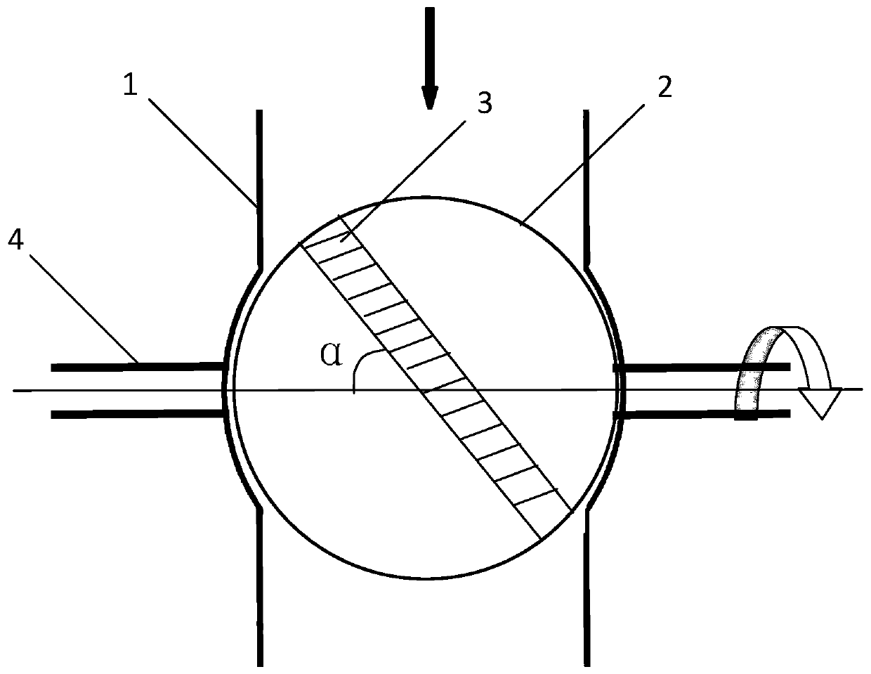
[0035] The angle α between the direction of a circle of grooves 3 on the surface of the spherical body 2 and the transverse axis is determined to be 15°C, and the different rotation speeds of the spherical body 2 are accurately measured and calibrated with an invalid Ti-based catalyst. The specific process is to place the spherical body 2 The rotation speed is set to 2 rpm, 4 rpm, 6 rpm, 7 rpm, 8 rpm, 9 rpm, 10 rpm, 12 rpm, 14 rpm Min, 16 rpm, 20 rpm, 30 rpm, measure the amount of catalyst feed in 5 minutes, 10 minutes, 15 minutes, 30 minutes, 1 hour, and take the average, and then draw the The relationship curve between the amount of catalyst feed and the rotation speed of the spherical body 2, and determine its relationship formula. Obtain the relational curve or relational expression of this kind of catalyst feeding amount and spherical body 2 rotational speeds, determine that can by adjusting the rotating speed of spherical body 2, carry out accurate metering and control t...

Embodiment 2

[0037] The angle α between the direction of a circle of grooves 3 on the surface of the spherical body 2 and the transverse axis is determined to be 20°C, and the different rotation speeds of the spherical body 2 are accurately measured and calibrated with an invalid Cr-based catalyst. The specific process is to place the spherical body 2 The rotation speed is set to 2 rpm, 4 rpm, 6 rpm, 7 rpm, 8 rpm, 9 rpm, 10 rpm, 12 rpm, 14 rpm Min, 16 rpm, 20 rpm, 30 rpm, measure the amount of catalyst feed in 5 minutes, 10 minutes, 15 minutes, 30 minutes, 1 hour, and take the average, and then draw the The relationship curve between the amount of catalyst feed and the rotation speed of the spherical body 2, and determine its relationship formula. Obtain the relationship curve or relational expression of this kind of catalyst feeding amount and spherical body 2 rotational speeds, confirm that can now by adjusting the rotating speed of spherical body 2, carry out accurate metering and contr...

Embodiment 3

[0039]The angle α between the direction of a circle of grooves 3 on the surface of the spherical body 2 and the transverse axis is determined to be 30°C, and the different rotation speeds of the spherical body 2 are accurately measured and calibrated with an invalid metallocene catalyst. The specific process is that the spherical body 2 The rotation speed is set to 2 rpm, 4 rpm, 6 rpm, 7 rpm, 8 rpm, 9 rpm, 10 rpm, 12 rpm, 14 rpm Min, 16 rpm, 20 rpm, 30 rpm, measure the amount of catalyst feed in 5 minutes, 10 minutes, 15 minutes, 30 minutes, 1 hour, and take the average, and then draw the The relationship curve between the amount of catalyst feed and the rotation speed of the spherical body 2, and determine its relationship formula. Obtain the relationship curve or relational expression of this kind of catalyst feeding amount and spherical body 2 rotational speeds, confirm that can now by adjusting the rotating speed of spherical body 2, carry out accurate metering and control...


PUM


Abstract

The invention discloses a rotary feeder of solid polyolefin catalysts. The rotary feeder of solid polyolefin catalysts comprises a housing, a ball body, and a connecting shaft; a cavity is formed in the housing; the surface of the ball body is provided with a circular groove; the ball body is arranged in the cavity, is pressed against the cavity firmly, and is capable of rolling in the cavity along the transverse direction axis; the connecting shaft is arranged on the transverse direction axis of the ball body; the housing is provided with a hole corresponding to the connecting shaft; and theconnecting shaft is designed to penetrate the hole. The rotary feeder is simple in structure, is capable of realizing introduction of solid polyolefin catalyst particles into a polymerization reactorcontinuously, smoothly, and accurately, polyolefin production cost is reduced, and equipment maintenance is convenient.

Description

technical field [0001] The invention relates to the field of olefin polymerization, in particular to a feeder for granular solid polyolefin catalysts. Background technique [0002] At present, most of the catalysts used in olefin polymerization in industry are solid particle type, and the feeding of this solid particle type catalyst is usually added by a specially designed catalyst feeding device, such as the solid catalyst feeding device adopted on the Unipol polyethylene device; there is also a After a complex preparation process, the catalyst is prepared into a certain concentration of slurry or paste, and then sent into the reactor with a metering system. In the above two methods, the equipment investment of the former is very high, the adding process is easy to block, and there is no accurate and effective method to know the catalyst content in the catalyst feeder. The preparation process of the latter is extremely complicated, and the preparation of a single catalyst ...

Claims


Application Information

Patent Timeline
Patent Type & Authority Patents(China)
IPC IPC(8): C08F2/01C08F10/00B01J4/00
CPCB01J4/007C08F2/01C08F10/00
Inventor 西晓丽郭峰王登飞李瑞王熺国海峰柳建伟赵兴龙高宇新宋磊杨国兴付义王斯晗姜进宪吕红丽王立明闫磊磊
Owner PETROCHINA CO LTD
Why Eureka
Try Eureka