A Satellite Electronic System Architecture Adapting to On-orbit Dynamic Configuration

A dynamic configuration, electronic system technology, applied in the field of spacecraft, can solve the problems of reduced resource utilization, satellites cannot achieve on-orbit transformation, repeated equipment, etc., to improve resource utilization, facilitate porting and reuse, and meet application requirements. Effect

Active Publication Date: 2021-04-06
SHANDONG INST OF AEROSPACE ELECTRONICS TECH
View PDF4 Cites 0 Cited by
  • Summary
  • Abstract
  • Description
  • Claims
  • Application Information

AI Technical Summary

Problems solved by technology

This electronic system architecture mainly includes time-division multiplexed data bus, standard onboard computer, standard development language and standard external unit RTU. In order to realize various functions of the subsystem, each subsystem needs to have its own controller, Sensors and actuators, which will easily lead to the extreme complexity of the entire system, will also lead to a large number of unnecessary repetitive equipment in the system, and the resource utilization rate will be reduced. Moreover, once the design is qualitative, the functions completed by the satellite cannot be changed on-orbit. There are defects such as single function, inability to adapt to the changing needs of users, and low user experience

Method used


Image

  • A Satellite Electronic System Architecture Adapting to On-orbit Dynamic Configuration
  • A Satellite Electronic System Architecture Adapting to On-orbit Dynamic Configuration
  • A Satellite Electronic System Architecture Adapting to On-orbit Dynamic Configuration

Examples


Embodiment 1

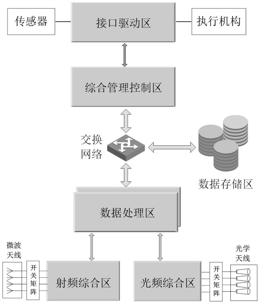
[0030] A satellite electronic system architecture adapted to on-orbit dynamic configuration, which includes six areas: integrated management and control area, data calculation and processing area, data storage area, radio frequency integrated area, optical frequency integrated area and interface drive area, among which the integrated The management control area, data calculation processing area, and data storage area are interconnected through the data exchange network.

[0031] in particular:

[0032] (1) Comprehensive management and control area, including management and control computer, program memory and bus interface, users can complete corresponding functions through the application program running on the management and control computer;

[0033] Among them, the program memory is mainly used to store operating systems and application programs, and the bus interface is the interface for data interaction between the integrated management control area, data storage area, a...

Embodiment 2

[0043] This embodiment provides a satellite electronic system architecture adapted to dynamic configuration on orbit, and divides the satellite electronic system into six areas: integrated management control area, interface driver area, data storage area, data calculation and processing area, radio frequency integrated area and optical frequency area. The comprehensive area, the integrated management control area, the data storage area and the modules of the data calculation and processing area all exchange data through the switching network. The switching network is a full-duplex network with multiple data exchange interfaces. The data bus is respectively connected with the radio frequency integrated area and the optical frequency integrated area. The radio frequency integrated area and the optical frequency integrated area are respectively connected with the microwave antenna array and the optical antenna array.

[0044] The specific implementation process is as follows: the m...

Embodiment 3

[0055] In order to have a clearer description of the architecture, the following is an example of a satellite electronic system architecture adapted to on-orbit dynamic configuration for the realization of commonly used functions of satellites.

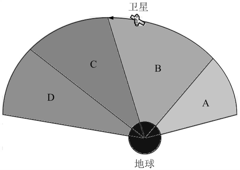
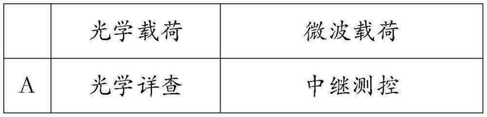
[0056] Such as figure 2 As shown, the satellite passes through four regions A, B, C, and D in sequence in orbit. Region A is overseas, region B is far sea, region C is offshore, and region D is domestic. The functions that the satellites cannot be assigned to the four regions are shown in the table.

[0057] Table: Function table of different flight phases of the satellite

[0058]

[0059]

[0060] First, the integrated management and control computer performs mission planning according to the tasks to be performed in each area, forms a mission planning scheme, and further decomposes the task sequence into detailed control instruction sequences according to the satellite system composition, functions and constraints.

[0061...


PUM


Abstract

The invention provides a satellite electronic system framework adapted to dynamic configuration on orbit, and divides the satellite electronic system into six areas, the comprehensive management control area is responsible for the most basic management and control functions of the satellite; the interface drive area is connected to the module by sensors and the drive module of the actuator; the data storage area is composed of a large-capacity memory with file management capabilities, responsible for data storage; the data processing area is composed of multiple high-performance processor modules with the same configuration, and each processor module can The application waveform is loaded and removed according to the needs, so as to realize the dynamic configuration of its functions; the radio frequency integrated area and the optical frequency integrated area are respectively connected with the microwave antenna array and the optical antenna array. The satellite electronic system architecture adapted to dynamic on-orbit configuration provided by the present invention can adapt to changes in application scenarios and dynamically change functions on-orbit, thereby realizing multiple uses of one satellite and improving the utilization rate of satellite resources.

Description

technical field [0001] The invention belongs to the technical field of spacecraft, and in particular relates to a satellite electronic system framework adapted to dynamic configuration on orbit. Background technique [0002] The technology of the spaceborne data management system has been widely applied to the satellites that have been launched, and a unified standard has been formed for the spaceborne data management system in my country. The spacecraft data management system is mainly composed of a central processing unit (CTU, Central Terminal Unit), a remote control unit, a telemetry unit, and several remote units (RTU, Remote Terminal Unit) and other equipment and software. These devices are connected to each other through the serial data bus, and jointly complete the functions of data transmission, processing, storage and management on the spacecraft. Large-scale spacecraft, such as the data management subsystem of a manned spacecraft, and the data management subsyste...

Claims


Application Information

Patent Timeline
Patent Type & Authority Patents(China)
IPC IPC(8): H04B7/185H04B10/118H04L29/08H04W4/38H04B7/0413
CPCH04B7/0413H04B7/18519H04B10/118H04L67/12
Inventor 马宗峰曲志超宋光磊张琦蔡卓燃
Owner SHANDONG INST OF AEROSPACE ELECTRONICS TECH
Why Eureka
Try Eureka