
Power socket convenient to plug in and plug out for robot and plug-in and plug-out method of power socket

A power socket and robot technology, applied in the field of robots, can solve the problems of difficult control of plugging and unplugging, affecting contact reliability, reducing strength and service life, etc., to achieve the effect of convenient operation, prolong service life, and avoid wear or deformation.

Inactive Publication Date: 2018-06-22
佛山市南海惠家五金制品有限公司
View PDF5 Cites 9 Cited by
  • Summary
  • Abstract
  • Description
  • Claims
  • Application Information

AI Technical Summary

Problems solved by technology

[0003] 1. Miniaturized design is likely to cause poor contact of the product, resulting in reduced strength and life;
[0004] 2. Repeated plugging and unplugging, the plugging force is not easy to control; too small plugging force will affect the reliability of the contact, too large plugging force is not conducive to plugging, and it is easy to cause damage to the connector;
[0005] 3. When the robot is overhauled, it needs to be disconnected, but because the plug and socket are in the mated state for a long time, especially after the number of pins increases, it takes a lot of force to pull it out

Method used


Image

  • Power socket convenient to plug in and plug out for robot and plug-in and plug-out method of power socket

Examples


Embodiment Construction

[0018] The following will clearly and completely describe the technical solutions in the embodiments of the present invention with reference to the accompanying drawings in the embodiments of the present invention. Obviously, the described embodiments are only some, not all, embodiments of the present invention.

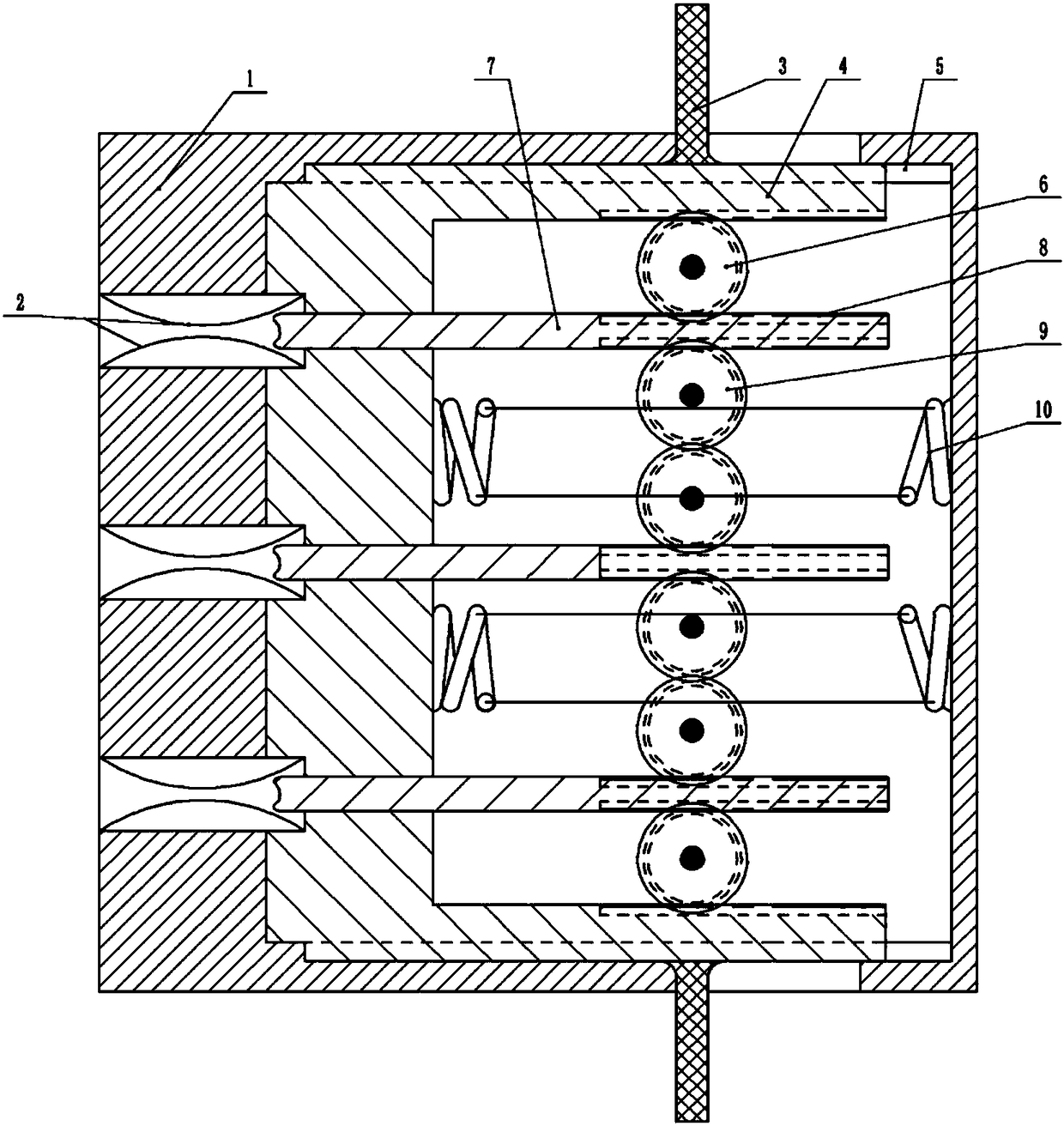
[0019] Such as figure 1 As shown, the robot uses a power socket that is easy to plug and unplug, including a shell 1. There are a number of jacks on one side of the shell 1. A pressure plate 4 is arranged in the shell 1 opposite to the jacks. An arc-shaped conductive reed 2, one end of the arc-shaped conductive reed 2 is fixedly connected to the jack, the other end of the arc-shaped conductive reed 2 is fixedly connected to the pressure plate 11, and the inner wall of the shell 1 is provided with a chute 5, and the pressure plate 4 is fixedly connected. A slider matching the chute 5 is arranged on the outer edge, the chute 5 is arranged along the direction of plug in...


PUM


Abstract

The invention relates to the technical field of a robot, in particular to a power socket for a robot and a plug-in and plug-out method of the power socket. In the power socket, jacks are formed in oneside of a shell, a press plate is arranged in the shell, two arc conductive spring sheets are arranged in each jack, one end of each arc conductive spring sheet is fixedly connected with the jack, the other ends of the arc conductive spring sheets are fixedly connected with the press plate, sliding grooves are formed in an inner wall of the shell, sliding blocks are arranged at edges of the pressplate and match with the sliding grooves, handles on the press plate extend out of the shell, springs are connected with the inner wall of the shell and the press plate, a through hole is formed in aposition, corresponding to the jack, of the press plate, a top needle is arranged in a through hole, two racks are symmetrically arranged at a tail part of the top needle, the above rack is correspondingly engaged and connected with a first gear, the below rack is correspondingly engaged and connected with a second gear, and the first gear at the optimal edge and the second gear at the optimal edge are respectively engaged with racks arranged at side edges of the press plate. By the power socket, the service lifetime can be prolonged, the plug-in and plug-out force is reduced, and the power socket is favorable in contact.

Description

technical field [0001] The invention relates to the technical field of robots, in particular to a power socket and a plugging method for a robot. Background technique [0002] In many robot fields, high-voltage power supplies are often used as the power source, and the connectors of the power supply, as the components connected to the power supply of the robot, need to have the characteristics of miniaturization. But there is following problem in the connection socket of existing power supply: [0003] 1. Miniaturized design is likely to cause poor contact of the product, resulting in reduced strength and life; [0004] 2. Repeated plugging and unplugging, the plugging force is not easy to control; too small plugging force will affect the reliability of the contact, too large plugging force is not conducive to plugging, and it is easy to cause damage to the connector; [0005] 3. When repairing the robot, it needs to be disconnected, but because the plug and socket are in ...

Claims


Application Information

Patent Timeline
Patent Type & Authority Applications(China)
IPC IPC(8): H01R13/11H01R13/20H01R13/629H01R13/633H01R13/639H01R43/26
CPCH01R13/639H01R13/11H01R13/20H01R13/629H01R13/6335H01R43/26
Inventor 陈永恒
Owner 佛山市南海惠家五金制品有限公司
Learn More