Magnetorheological fluid characteristic tester

A magnetorheological fluid and tester technology, which is used in the measurement of magnetic properties, measuring magnetic variables, instruments, etc., can solve the problems of magnetorheological fluid shear strain rate limitation, transmission error, measurement result deviation, etc. Links and human errors, ensuring stability and reliability, and the effect of stable and reliable linear errors

Active Publication Date: 2018-06-22
CHINA UNIV OF MINING & TECH
View PDF7 Cites 3 Cited by
  • Summary
  • Abstract
  • Description
  • Claims
  • Application Information

AI Technical Summary

Problems solved by technology

[0003] The commercial yield stress testers currently on the market are mainly foreign products and are expensive. There is no standard method for the yield stress test of magnetorheological fluids in China. The lack of systematization and incomplete testing have hindered the further development of magnetorheological fluids. Research and commercialization of magnetorheological products; currently known magnetorheological fluid characteristic testers are limited by coils, and the radius of rotation is small, so the shear strain rate of magnetorheological fluid is limited and cannot be completed under high shear rates. In addition, there are many transmission parts between the power part and the shearing part, which may easily cause transmission errors and cannot guarantee the reliability of the measurement accuracy; the existing heating method of the magnetorheological fluid measuring instrument has a slow heating process, and the shearing device Magneto-rheological fluid conducts heat unevenly, causing deviations in measurement results

Method used


Image

  • Magnetorheological fluid characteristic tester
  • Magnetorheological fluid characteristic tester
  • Magnetorheological fluid characteristic tester

Examples


Embodiment Construction

[0032] The present invention will be further described below in conjunction with accompanying drawing.

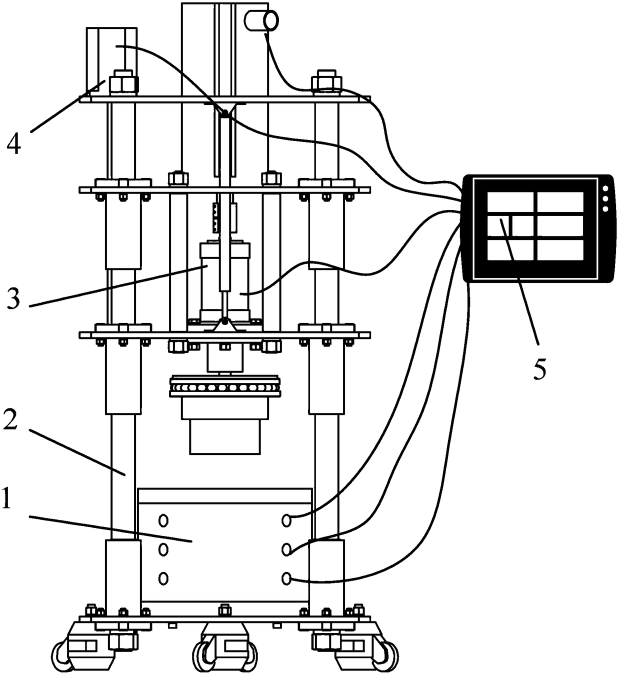
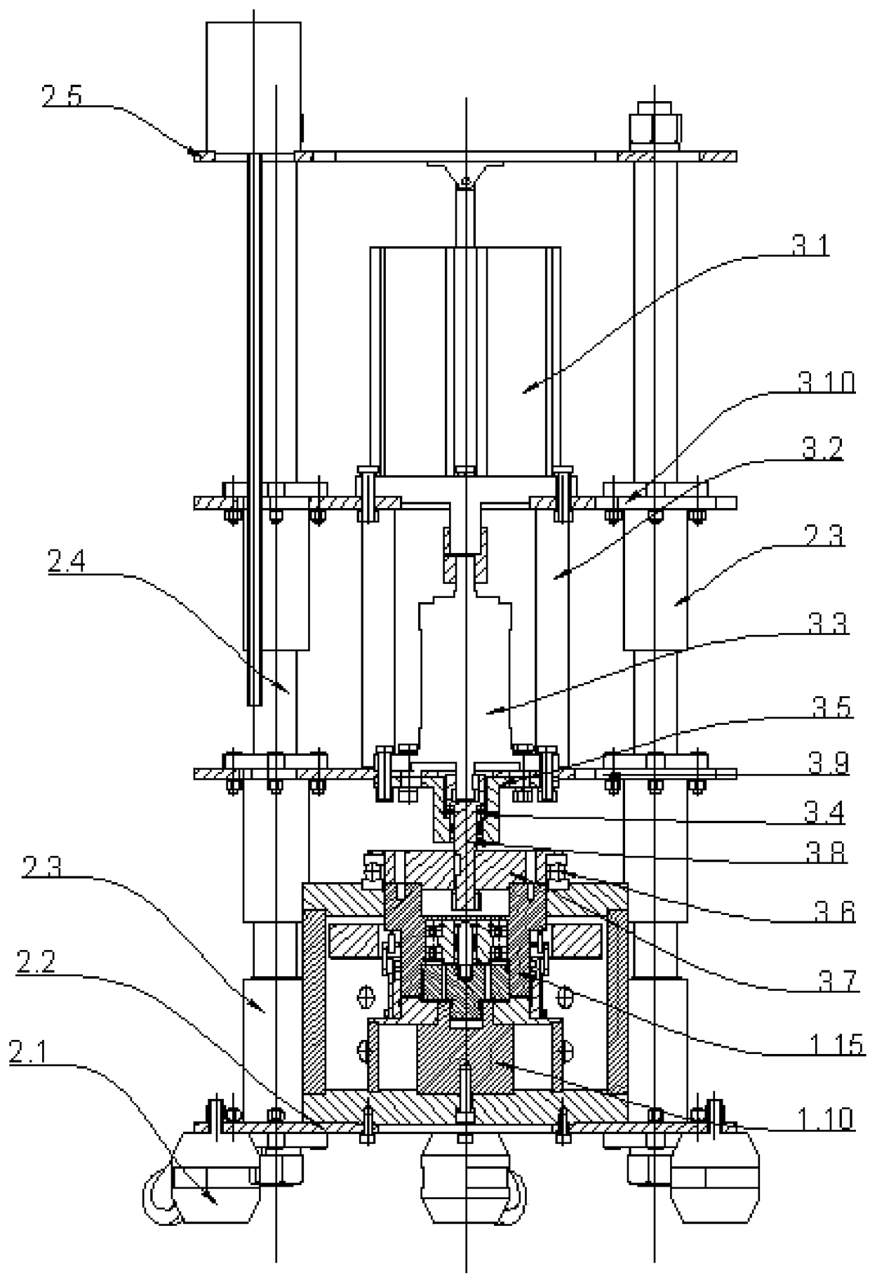
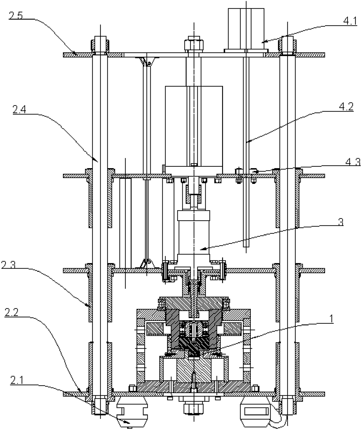
[0033] Such as Figure 1 to Figure 5 As shown, a magneto-rheological fluid characteristic tester includes a shearing device 1, a frame device 2, a transmission device 3, a lifting device 4, and a control measuring device;

[0034]The shearing device 1 includes a magnetic circuit device and a magnetorheological fluid 1.20, wherein the magnetic circuit device includes a shell composed of a magnetic circuit bottom plate 1.7, a magnetic circuit outer wall 1.2 and a magnetic circuit board 1.1, and an upper magnetic core 1.15 and a lower magnetic core are arranged in the shell. A magnetic core, the outer periphery of the magnetic core is provided with a magnetic isolation ring 1.5, the upper end of the magnetic isolation ring 1.5 is equipped with a coil mounting bracket 1.4, and the coil 1.3 is set outside the upper magnetic core 1.15 and placed on the coil mounting bracket 1.4, ...


PUM


Abstract

The invention discloses a magnetorheological fluid characteristic tester, including a rack device, a transmission device, a lifting device, a shearing device and a control measurement device. Torque and rotating speed required by rotation are provided through a main motor, and a dynamic torque sensor is directly connected with the main motor; an upper shearing disc transmits shear yield stress tothe torque sensor through an upper magnetic core; the lifting device mainly comprises a lifting motor and a ball screw, and a lead screw nut at the lower end is connected with an electrical support ina transmission part; and the shearing device consists of a magnetic circuit, a coil, a heating device and a magnetism isolation sealing component. The magnetorheological fluid characteristic tester has the advantages of simple structure, convenient operation, high safety and complete functions, and is relatively wide in measurement range; a trapezoid magnetic circuit structure is adopted, and themagnetic circuit is stable and uniform; a motor lifting control scheme is adopted, thereby realizing automatic control of detection; a multi-input heating mode is adopted, and the temperature is adjustable and controllable; and a sand bath heating mode is adopted, stability and reliability are achieved, and controllable temperature is high.

Description

technical field [0001] The invention relates to a magnetorheological fluid characteristic tester, which belongs to the technical field of magnetorheological fluid research equipment. Background technique [0002] Magnetorheological fluid is a suspension formed by dispersing micron or nanoscale magnetic particles in a specific liquid, and its main components include magnetic particles, carrier liquid and various additives. The main working principle of the magnetorheological fluid is: when there is no magnetic field, the magnetic particles of the magnetorheological fluid undergo random Brownian motion; after the magnetic field is applied, the magnetic particles in the magnetorheological fluid aggregate along the direction of the magnetic field to form chain, the whole is in a semi-solid state showing non-Newtonian fluid characteristics; after the magnetic field is withdrawn, the magnetorheological fluid returns to a suspension liquid state showing Newtonian fluid characterist...

Claims


Application Information

Patent Timeline
IPC IPC(8): G01R33/07G01R33/12
CPCG01R33/07G01R33/12
Inventor 陈飞王戈田祖织王书友韩猛猛邓永瑞李昊鹏
Owner CHINA UNIV OF MINING & TECH
Why Eureka
Try Eureka