
Thread sealing coupling

A thread seal and coupling technology, applied in the direction of couplings, elastic couplings, mechanical equipment, etc., can solve problems affecting normal use, affecting service life, and many sealing links

Inactive Publication Date: 2018-06-22
ZHENJIANG SUBAIXIN CONSTR MACHINERY CO LTD
View PDF0 Cites 1 Cited by
  • Summary
  • Abstract
  • Description
  • Claims
  • Application Information

AI Technical Summary

Problems solved by technology

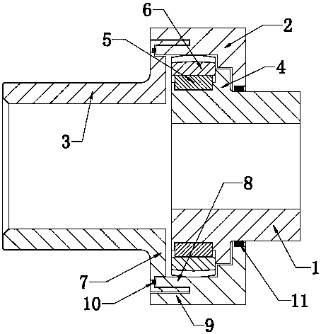
[0002] The traditional drum-shaped gear coupling generally includes two half-couplings, each half-coupling has an outer gear shaft and an inner gear sleeve sleeved outside the outer gear shaft, and the two half-couplings have The two inner gear sleeves are connected by flanges. As we all know, the coupling is generally sealed and installed through the end cover and the sealing ring during the connection process. The existing structure, on the one hand, due to the installation of the sealing ring, the sealing There are many links, and long-term use is easy to cause the sealing ring to fail, causing lubricating oil to leak, which reduces the reliability of use. In addition, the sealing ring needs to be replaced frequently, which wastes manpower and material resources and affects normal use. On the other hand, the terminal used The cover is directly placed on the shaft end, and it is easy to cause damage to the end cover after long-term use, which affects the service life

Method used


Image

  • Thread sealing coupling

Examples


Embodiment Construction

[0010] The threaded sealing coupling of the present invention will be described in further detail below in conjunction with the accompanying drawings and specific embodiments.

[0011] As shown in the figure, the thread-sealed coupling of the present invention includes left and right half-couplings respectively connected to two sections of rotating shafts and an inner gear sleeve 2 for installation between the left and right half-couplings, One end of the inner tooth sleeve 2 is open, and the other end has a setting hole equivalent to the outer diameter of the right half coupling. Two-stage stepped holes are formed in the inner cavity of the inner tooth sleeve 2. The end of the right half coupling 1 A limit step 4 is set, the front part of the limit step 4 is provided with a keyway and an outer gear sleeve 6 is installed on the half coupling through a key 5, and the right half coupling 1 passes through the placement hole of the inner gear sleeve and makes The limit step is lim...


PUM


Abstract

The invention discloses a thread sealing coupling which comprises a left-half coupling body, a right-half coupling body and an inner gear sleeve. One end of the inner gear sleeve is open, and the other end of the inner gear sleeve is provided with a placement hole. Two stages of stepped holes are formed in an inner cavity of the inner gear sleeve, and a limiting step is arranged at the tail end ofthe right-half coupling body. A key groove is formed in the front portion of the limiting step, and an outer gear sleeve is mounted on the right-half coupling body. The right-half coupling body penetrates the placement hole, and the outer gear sleeve is located in the inner cavity of the inner gear sleeve. An annular mounting end is arranged at the tail end of the left-half coupling body, and aninternal thread and an external thread are arranged on the inner side and the outer side of the annular mounting end. A threaded hole is formed in the opening end of the inner gear sleeve, and the left-half coupling body is mounted at the opening end of the inner gear sleeve. After the structure is adopted, sealing links are few, the sealing property is improved, the joint end and the inner cavityare staggered to further ensure the sealing property, and the threaded connection structure further ensures the sealing property and use for a long time of the thread sealing coupling; and structuraldesign is simple, dismounting and mounting are convenient and rapid, overhauling is convenient, the manufacturing cost is reduced, and the service life is prolonged.

Description

technical field [0001] The invention relates to a shaft coupling, in particular to a threaded sealing shaft coupling. Background technique [0002] The traditional drum-shaped gear coupling generally includes two half-couplings, each half-coupling has an outer gear shaft and an inner gear sleeve sleeved outside the outer gear shaft, and the two half-couplings have The two inner gear sleeves are connected by flanges. As we all know, the coupling is generally sealed and installed through the end cover and the sealing ring during the connection process. The existing structure, on the one hand, due to the installation of the sealing ring, the sealing There are many links, and long-term use is easy to cause the sealing ring to fail, causing lubricating oil to leak, which reduces the reliability of use. In addition, the sealing ring needs to be replaced frequently, which wastes manpower and material resources and affects normal use. On the other hand, the terminal used The cover ...

Claims


Application Information

Patent Timeline
IPC IPC(8): F16D3/50
CPCF16D3/50F16D3/185
Inventor 张长凤
Owner ZHENJIANG SUBAIXIN CONSTR MACHINERY CO LTD
Learn More