Eureka AIR delivers breakthrough ideas for toughest innovation challenges, trusted by R&D personnel around the world.

Blocking edge device for logistical-transport-tape type conveying machine

A technology of belt conveying and logistics transmission, which is applied in the directions of conveyors, transportation and packaging, loading/unloading, etc. It can solve the problems of no dust reduction, no angle adjustment, and difficult gathering of materials, so as to improve air quality, reduce scattering, good stability effect

Inactive Publication Date: 2018-06-22
杭州蔓漫文化创意有限公司
View PDF0 Cites 0 Cited by
  • Summary
  • Abstract
  • Description
  • Claims
  • Application Information

AI Technical Summary

Problems solved by technology

[0003] In the prior art, there are still many deficiencies in the edge retaining device for belt conveyors. It lacks the auxiliary dust suppression function, and cannot carry out dust suppression on the dust aroused by the material, which is easy to aggravate the pollution degree of the air in the working environment. At the same time, the existing The edge retaining device for belt conveyor has no angle adjustment function, and the bending angle of the rubber sheet cannot be adjusted according to the needs, which makes it difficult for materials to gather in the middle of the conveyor belt. Therefore, a new type of edge retaining device for belt conveyor is urgently needed to solve the above problems. The problem

Method used


Image

  • Blocking edge device for logistical-transport-tape type conveying machine
  • Blocking edge device for logistical-transport-tape type conveying machine
  • Blocking edge device for logistical-transport-tape type conveying machine

Examples


Embodiment Construction

[0020] In order to make the technical means, creative features, goals and effects achieved by the present invention easy to understand, the present invention will be further described below in conjunction with specific embodiments.

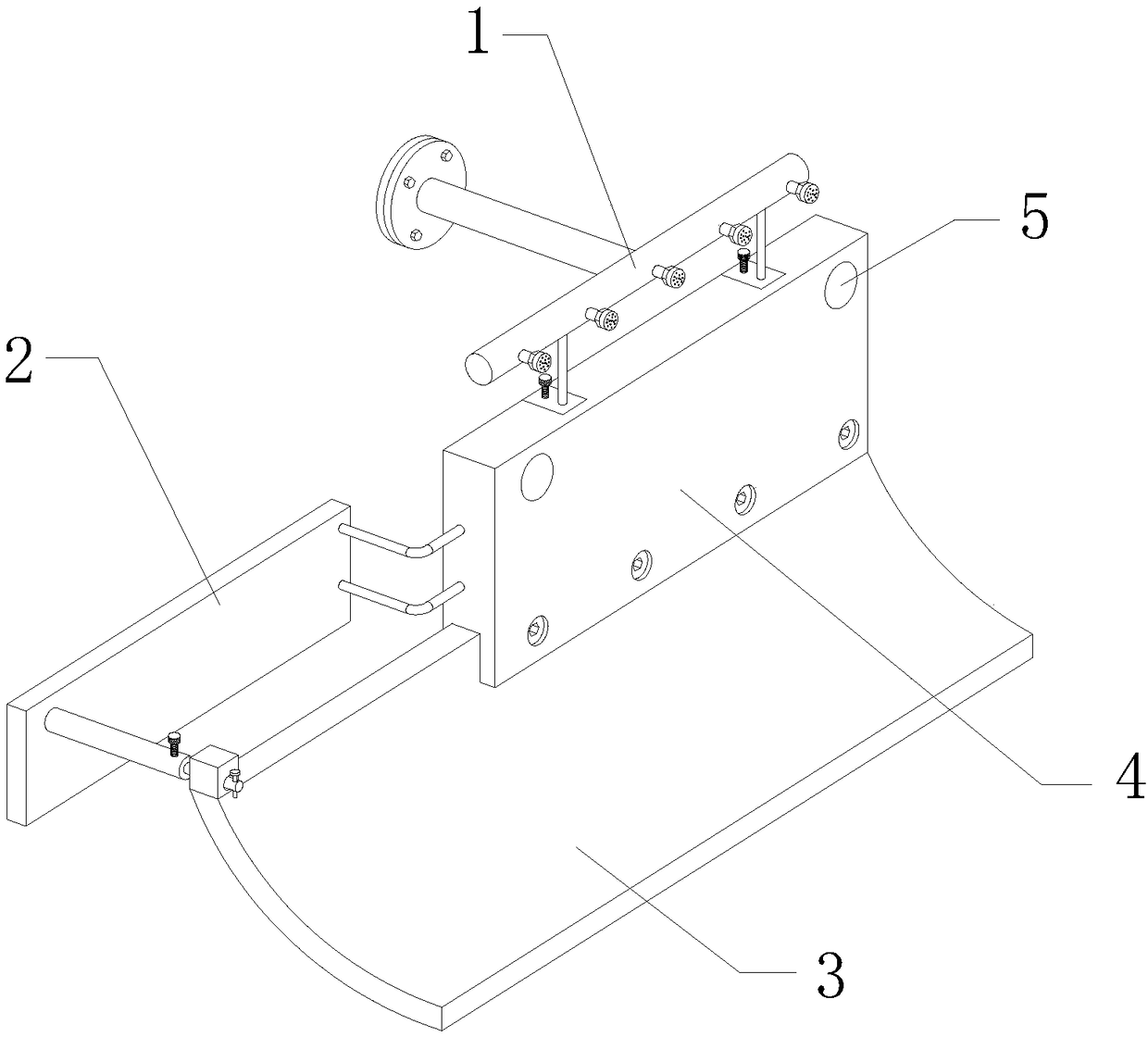
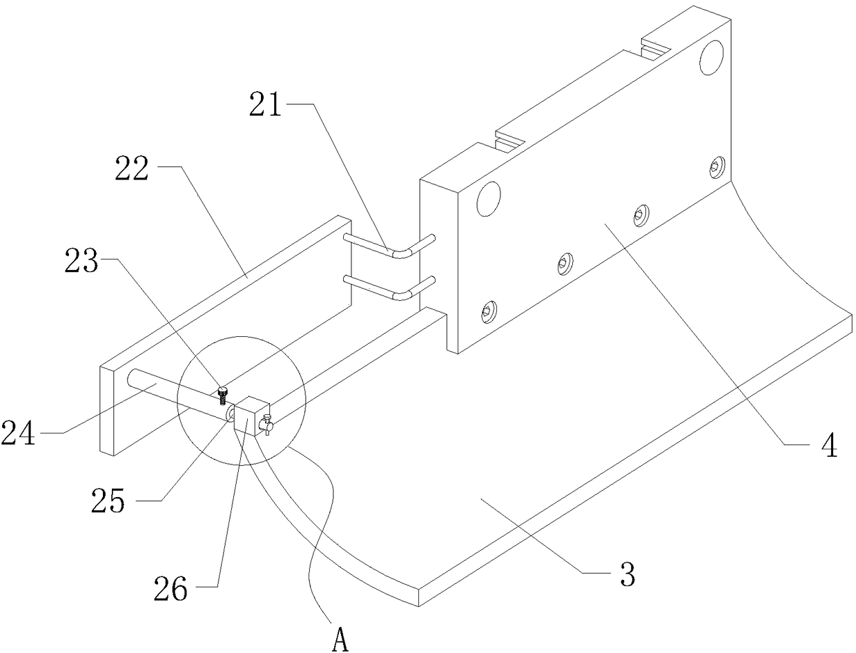
[0021] see Figure 1-Figure 4 , the present invention provides a technical solution: a sidewall device for a logistics conveyor belt conveyor, including a device main body, an auxiliary dust reduction mechanism 1 and an angle adjustment mechanism 2, and the device main body includes a rubber sheet 3, a baffle plate 4 and a fixing hole 5 , the fixing hole 5 is opened on the upper side of the front end surface of the baffle plate 4, and the rubber sheet 3 is assembled on the lower end surface of the baffle plate 4.

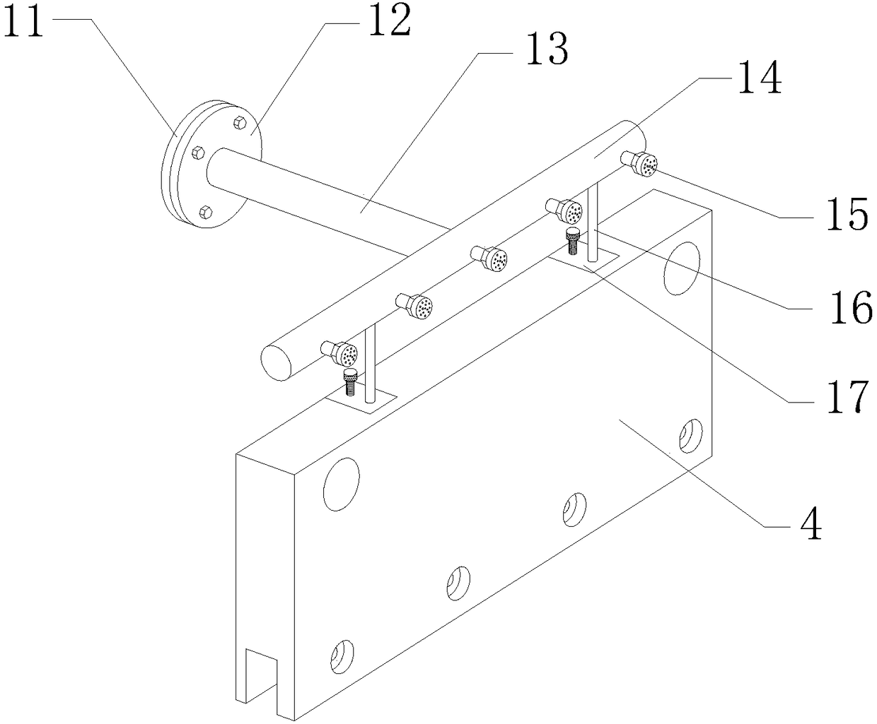
[0022] The auxiliary dust reduction mechanism 1 is assembled on the upper end surface of the baffle plate 4. The auxiliary dust reduction mechanism 1 includes a disc 11, a flange plate 12, a water injection pipe 13, a water distribution...


PUM


Abstract

The invention provides a blocking edge device for a logistical-transport-tape type conveying machine. The locking edge device for the logistical-transport-tape type conveying machine includes a flangeplate, a water injection pipe, a water distributing pipe, an atomizing sprinkler, fixed plates, sleeves, movable rods and rubber blocks, wherein the water distributing pipe is arranged on the upper side of a baffle, and the atomizing sprinkler is assembled on the front side of the annular side face of the water distributing pipe. The front end of the water injection pipe is arranged in the middleof the rear side of the annular side face of the water distributing pipe, and the flange plate is assembled at the rear end of the water injection pipe. The purpose of assisting to reduce dust is realized, the fixed plates are arranged on the rear sides of rubber sheets, and the fixed plates are mounted on the left end face of the baffle through connecting rods. The rear ends of the sleeves are fixed on the left sides of the front end faces of the fixed plates, the rear ends of the movable rods are embedded in the sleeves, and the front ends of the movable rods penetrate through the rubber blocks and extend to the front sides of the rubber blocks. The purpose of adjusting the bending angle of the rubber sheets is realized. The locking edge device for the logistical-transport-tape type conveying machine has the function of assisting to reduce the dust, and is capable of achieving material gathering, good in stability and high in reliability.

Description

technical field [0001] The invention relates to an edge retaining device for a logistics transmission belt conveying machine, which belongs to the technical field of logistics transporting machinery. Background technique [0002] Conveying machinery such as belt conveyors are widely used in industrial production. In order to prevent materials from falling when entering the conveyor, most existing conveyors are provided with baffles, and the top of the baffle is fixed on the frame on the side of the conveyor, and the bottom is lapped on the conveyor belt of the conveyor. [0003] In the prior art, there are still many deficiencies in the edge retaining device for belt conveyors. It lacks the auxiliary dust suppression function, and cannot carry out dust suppression on the dust aroused by the material, which is easy to increase the pollution degree of the air in the working environment. At the same time, the existing The edge retaining device for belt conveyor has no angle ad...

Claims


Application Information

Patent Timeline
Patent Type & Authority Applications(China)
IPC IPC(8): B65G21/20B65G69/18B65G69/20B01D47/06
CPCB65G21/2063B01D47/06B65G69/18B65G69/20
Inventor 不公告发明人
Owner 杭州蔓漫文化创意有限公司
Why Eureka
Eureka Blog
Learn More