Push type medical feeder

A technology for medical and feeding devices, which is applied in the field of medical equipment, can solve the problems of low maintenance cost, food clogging pipes, and large limitations, and achieve the effects of strong practicability, prevention of re-injury, and strong controllability

Pending Publication Date: 2018-06-22
沙蕊
View PDF8 Cites 2 Cited by
  • Summary
  • Abstract
  • Description
  • Claims
  • Application Information

AI Technical Summary

Problems solved by technology

[0002] my country Patent No. CN201620883585.0 discloses an intensive care feeder with automatic feeding function. The feeder at least includes a feeder body and a delivery device connected to the feeder body through a pipeline. The top surface of the feeder body is left and right. A control box and a feeding port are respectively installed at the ends of the feeder. A drive motor is provided at the middle of the top surface of the main body of the feeder. The output shaft of the drive motor is fixedly connected to the stirring column. The left and right walls of the main body of the food container are equipped with heating rods. The beneficial effects of the utility model are: the intensive care feeder with automatic feeding function can feed the patient in an orderly manner through the small crank connecting rod structure, not only does not require medical care The care of personnel can also automatically adjust the temperature of things, which has met the needs of patients. At the same time, the device can stir the food by itself to prevent the food from being too sticky. The above-mentioned device uses food under the action of gravity to realize eating, and there are two major defects, one is poor in controlling the flow speed of food, and the other is prone to the phenomenon of food blocking the pipeline, which has relatively large limitations

Method used


Image

  • Push type medical feeder
  • Push type medical feeder
  • Push type medical feeder

Examples


Embodiment Construction

[0017] The following will clearly and completely describe the technical solutions in the embodiments of the present invention with reference to the accompanying drawings in the embodiments of the present invention. Obviously, the described embodiments are only some, not all, embodiments of the present invention. Based on the embodiments of the present invention, all other embodiments obtained by persons of ordinary skill in the art without making creative efforts belong to the protection scope of the present invention.

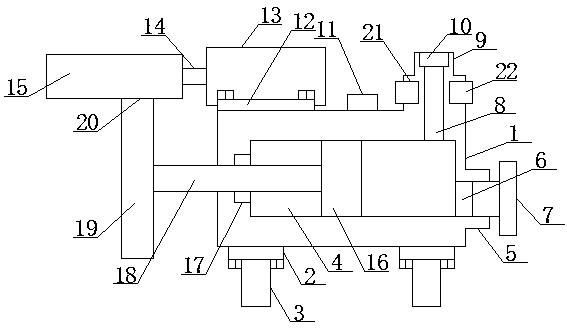
[0018] see figure 1 , an embodiment provided by the present invention: comprising a main hollow shell 1, the bottom of the main hollow shell 1 is fixed with a plurality of main connecting plates 2 by bolts, and the bottom of each of the main connecting plates 2 is equipped with supporting legs 3. A food storage space 4 is provided in the center of the main hollow casing 1, and a food passage 5 with an integrated structure is provided on one side of the main ho...


PUM


Abstract

The invention discloses a push type medical feeder. The push type medical feeder comprises a main hollow case, the bottom of the main hollow case is fixedly provided with a plurality of main connecting plates through bolts, the bottom of every main connecting plate is provided with a support leg, the internal center of the main hollow case is provided with a food storage space, and one side of themain hollow case is provided with a food through pipe in an integrated structure. The p push type medical feeder is in a push type structure, a motor drives a threaded structure, and through the intervals of threads of the threaded structure, achieves the feature of rotation type pushing, thereby effectively avoiding food blocking; meanwhile, the push type medical feeder can control the rotatingspeed of the motor to control the food discharging speed, thereby being high in controllability. Besides, the push type medical feeder comprises an electric food heating mechanism, which can ensure the temperature of discharged food and avoid second injury of a patient due to overlow food temperature, thereby being high in practicality.

Description

technical field [0001] The invention relates to the technical field of medical devices, in particular to a medical push feeder. Background technique [0002] my country Patent No. CN201620883585.0 discloses an intensive care feeder with automatic feeding function. The feeder at least includes a feeder body and a delivery device connected to the feeder body through a pipeline. The top surface of the feeder body is left and right. A control box and a feeding port are respectively installed at the ends of the feeder. A drive motor is provided at the middle of the top surface of the main body of the feeder. The output shaft of the drive motor is fixedly connected to the stirring column. The left and right walls of the main body of the food container are equipped with heating rods. The beneficial effects of the utility model are: the intensive care feeder with automatic feeding function can feed the patient in an orderly manner through the small crank connecting rod structure, not ...

Claims


Application Information

Patent Timeline
IPC IPC(8): A61J15/00
CPCA61J15/0011A61J15/0076A61J2200/42
Inventor 沙蕊
Owner 沙蕊
Why Eureka
Try Eureka