Large-caliber umbrella antenna deployment mechanism

An umbrella-shaped antenna and deployment mechanism technology, which is applied in the field of large-diameter umbrella-shaped antenna deployment mechanism, can solve the problems of excessive volume, poor synchronization, and low reliability, and achieve the effects of small volume, large output torque, and wide application range

Active Publication Date: 2018-06-19
XIAN INSTITUE OF SPACE RADIO TECH
View PDF8 Cites 3 Cited by
  • Summary
  • Abstract
  • Description
  • Claims
  • Application Information

AI Technical Summary

Benefits of technology

This patented technology solves problems associated with traditional methods used on high-powered radar systems such as extending or collapsible an elongated metal tube called a pole (pole). These issues include safety concerns due to excessive force from outside sources like wind) and reliability issues when deployable at longer distances. By utilizing this new design, these technical improvements improve performance over existing designs while reducing their size and cost compared to previous solutions.

Problems solved by technology

This patented technical problem addressed by this patents relates to improving the performance (power) efficiency or durability of high-aperture radar systems used on truss structures satellites due to their limited space requirements.

Method used


Image

  • Large-caliber umbrella antenna deployment mechanism
  • Large-caliber umbrella antenna deployment mechanism
  • Large-caliber umbrella antenna deployment mechanism

Examples


Embodiment Construction

[0027] In order to make the solution of the present invention clearer, the present invention will be further described below in conjunction with the accompanying drawings and specific embodiments:

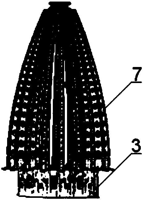
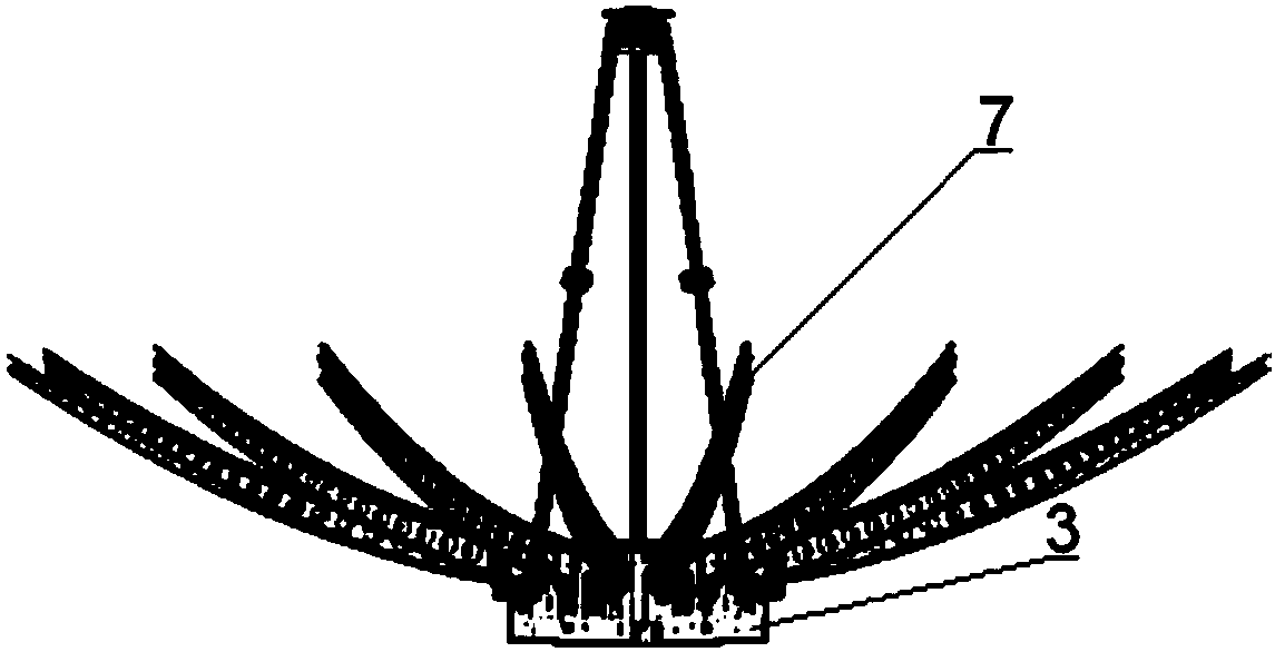
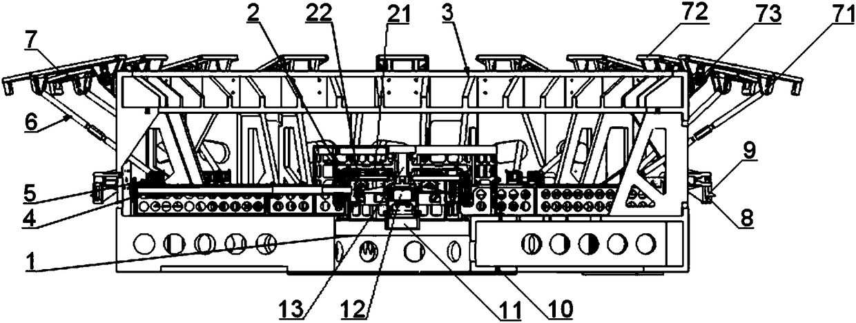
[0028] Such as Figure 1~4 As shown, a large-diameter umbrella-shaped antenna deployment mechanism includes a driver 1, a bevel gear set 2, a support 3, a screw 4, a slider 5, a connecting rod 6, a rib assembly 7, a spring 8 and a stop pin 9; The seat 3 adopts a hollow cylindrical structure, and one end of the support 3 is installed with a driver 1 for providing power, and the inner side of the support 3 is provided with several lead screws 4 for transmitting power, and the driver 1 is connected to the lead screw 4 through the bevel gear set 2, A slider 5 is installed on the lead screw 4, which only translates along the axial direction of the lead screw 4; the other end of the support 3 is installed with a rib assembly 7 for assembling the antenna, and the rib assembly 7 is hinged ...


PUM


Abstract

The invention discloses a large-caliber umbrella antenna deployment mechanism which comprises a driver, a bevel gear set, a support, screw rods, sliders, connecting rods, rib assemblies, springs and stop pins. The support is a hollow cylinder structure. One end of the support is equipped with a driver for providing power, and a plurality of screw rods for transmitting power are arranged inside thesupport. The driver is connected to the screw rods through the bevel gear set, the screw rods are equipped with the sliders which are only in translational motion along the axial directions of the screw rods. The other end of the support is equipped with the rib assemblies for assembling an antenna, the rib assemblies are hinged to the sliders through the connecting rods, and the stop pins for locking the rib assemblies are pressed and installed at the outer side of the support through the springs. Through the cooperation of the driver, the bevel gear set, the support, the screw rods, the sliders, the connecting rods, the rib assemblies, the springs and the stop pins, the synchronous deployment of an umbrella antenna is achieved, a deployment torque is enhanced, a device volume is reduced, the safe and reliable deployment process is ensured, and shortcomings of a traditional umbrella antenna deployment mechanism are made up.

Description


Claims


Application Information

Patent Timeline
Owner XIAN INSTITUE OF SPACE RADIO TECH
Why Eureka
Try Eureka