Al technical title is built by PatSnap Al team. It summarizes the technical point description of the patent document.
A cage and mounting plate technology, which is applied to steam cooking utensils and other directions, can solve the problems of affecting sales, unstable control, and heavy cages, etc., and achieve the effects of shortening waiting time, improving work efficiency, and reducing workload.
Inactive Publication Date: 2018-06-19
侯一鸣
View PDF5 Cites 0 Cited by
Summary
Abstract
Description
Claims
Application Information
AI Technical Summary
This helps you quickly interpret patents by identifying the three key elements:
Problems solved by technology
Method used
Benefits of technology
Problems solved by technology
[0002] Steamed buns are a common food in people’s daily life. Steamed buns are often steamed in large quantities in steamed bun shops, so that they can be steamed and eaten. In order to keep warm and save space, the steamed buns are sold together in a cage during the sales process. However, in such a process, due to the need to take out the steamed buns in the cages of different heights, it is necessary to lift the upper cage at a certain angle. In the process of making buns, the cage is often overweight and the control force is unstable, causing the cage to be overturned, causing the buns to fall to the ground and affecting sales. At the same time, this process is cumbersome and a relatively heavy labor. Therefore, A cage auxiliary lifting device is needed
Method used
Image
Click on the blue label to locate the original text in one second.
Reading with bidirectional positioning of images and text.
Examples
Embodiment Construction
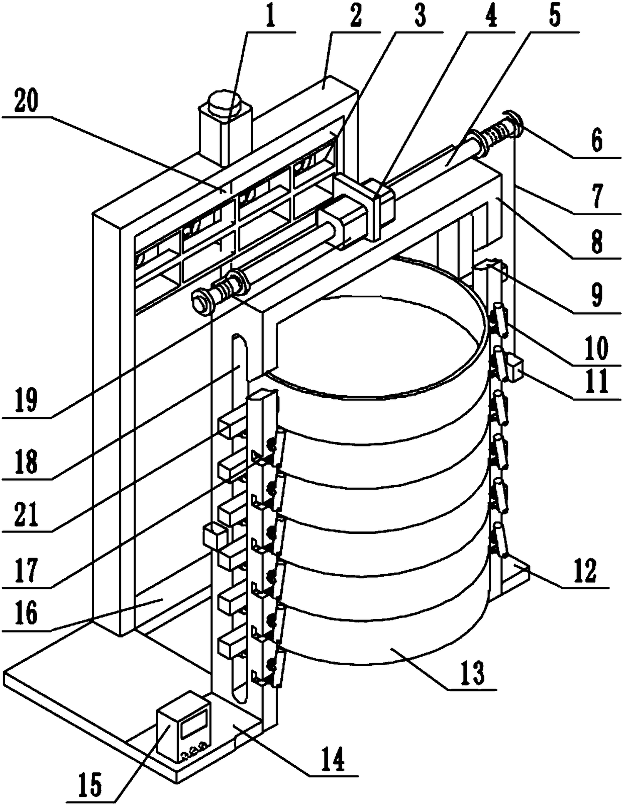
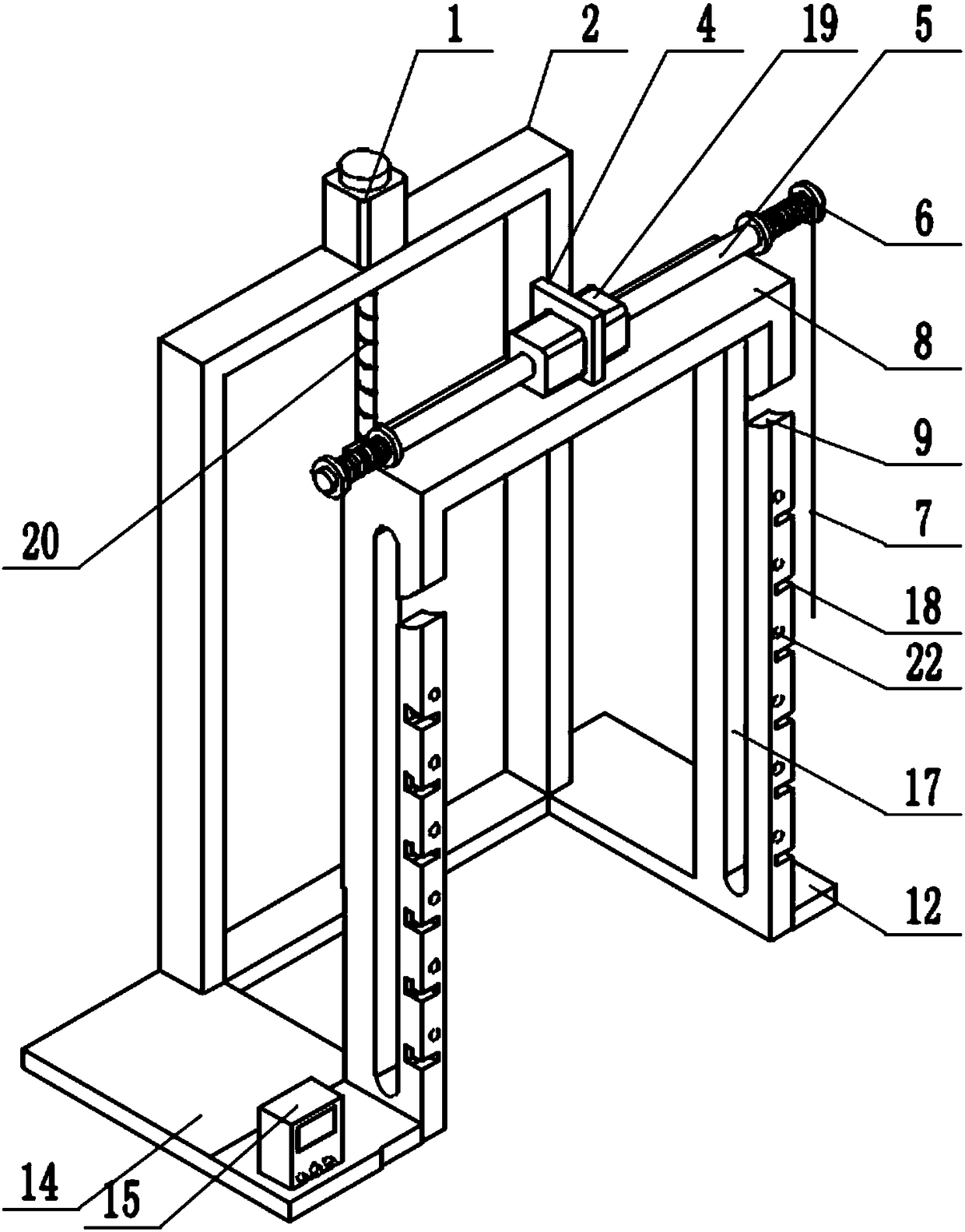
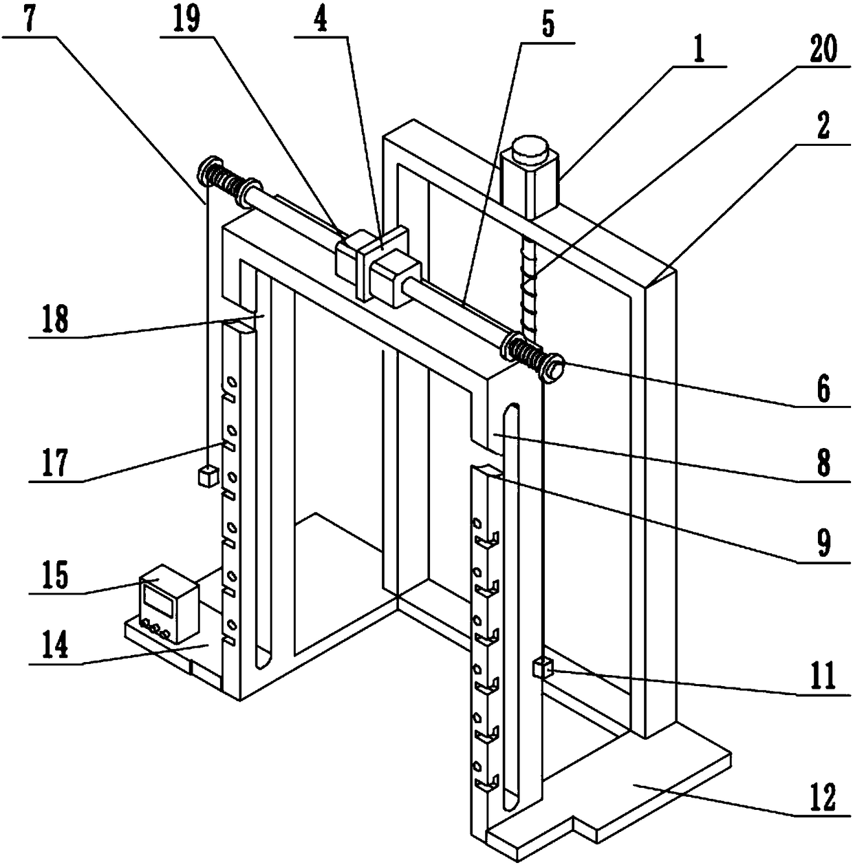
[0016] A cage auxiliary lifting device is composed of a stepping motor 1, a bracket 2, a guide assembly 3, a mounting plate 45, a rotating shaft 5, a hoisting roller 6, a hoisting rope 7, a frame 8, a pick-and-place opening 9, and a locking position Assembly 10, electromagnet 11, support plate 1 12, cage drawer 13, support plate 2 14, controller 15, connecting horizontal plate 16, card slot 17, sliding shaft 18, double-axis self-locking motor 19, lead screw 20, handle 21 Composed of matching holes 22, the stepper motor 1 is arranged in the middle of the two ends of the bracket, the output shaft of the stepper motor 1 is connected with a lead screw 20, and the end of the lead screw 20 is arranged on the connecting horizontal plate 16, connecting the horizontal plate 16 The two ends of the plate 16 are respectively connected with the support plate one 12 and the support plate two 14, the support plate one 12 and the support plate two 14 are provided with a frame 8, and the lead s...
PUM
Abstract
The invention discloses a food steamer auxiliary lifting device, and belongs to the field of kitchen and bath equipment. The food steamer auxiliary lifting device comprises a stepping motor, a support, a flow guiding assembly, an installing plate, a rotating shaft, a winding roll, a winding rope, a rack, picking and placing openings, clamping assemblies, electromagnets, a supporting plate I, foodsteamers, a supporting plate II, a controller, a connecting transverse plate, clamping grooves, sliding shafts, a double-shaft self-locking motor, a screw rod, handles and matching holes, wherein thestepping motor is arranged at the middle position of the upper end of the support; an output shaft of the stepping motor is connected with the screw rod; the tail end of the screw rod is arranged on the connecting transverse plate; two ends of the connecting transverse plate are respectively connected with the supporting plate I and the supporting plate II; the rack is arranged on the supporting plate I and the supporting plate II; the screw rod is matched with the flow guiding assembly; sliding grooves are formed in the middle positions of the side surfaces of the rack. The auxiliary liftingdevice disclosed by the invention has the advantages that the time for lifting the food steamers is shortened, steamed buns with stuffing in any food steamer can be more conveniently and quickly taken, and the waiting time of customers is shortened.
Description
technical field [0001] The invention relates to a cage auxiliary lifting device, in particular to a cage auxiliary lifting device which utilizes a mechanical structure to assist cage lifting, and belongs to the field of kitchen and bathroom equipment. Background technique [0002] Steamed buns are a common food in people’s daily life. Steamed buns are often steamed in large quantities in steamed bun shops, so that they can be steamed and eaten. In order to keep warm and save space, the steamed buns are sold together in a cage during the sales process. However, in such a process, due to the need to take out the steamed buns in the cages of different heights, it is necessary to lift the upper cage at a certain angle. In the process of making buns, the cage is often overweight and the control force is unstable, causing the cage to be overturned, causing the buns to fall to the ground and affecting sales. At the same time, this process is cumbersome and a relatively heavy labor....
Claims
Application Information
Patent Timeline
Application Date:The date an application was filed.
Publication Date:The date a patent or application was officially published.
First Publication Date:The earliest publication date of a patent with the same application number.
Issue Date:Publication date of the patent grant document.
PCT Entry Date:The Entry date of PCT National Phase.
Estimated Expiry Date:The statutory expiry date of a patent right according to the Patent Law, and it is the longest term of protection that the patent right can achieve without the termination of the patent right due to other reasons(Term extension factor has been taken into account ).
Invalid Date:Actual expiry date is based on effective date or publication date of legal transaction data of invalid patent.