
Method and circuit of determining wireless charging foreign matter based on Q value

A wireless charging and circuit technology, applied in the direction of circuit devices, electrical components, etc., can solve the problems of increasing system cost, affecting system efficiency, increasing circuit complexity, etc., achieving the effect of low cost, simple circuit structure, and guaranteed accuracy

Pending Publication Date: 2018-06-15
SHENZHEN CHIPSVISION MICRO CO LTD
View PDF0 Cites 5 Cited by
  • Summary
  • Abstract
  • Description
  • Claims
  • Application Information

AI Technical Summary

Problems solved by technology

However, the detection of Q value is carried out in the resonant frequency range, which will couple high voltage on the transmitting coil and receiving coil, which will cause irreversible damage to the equipment. In order to solve this problem, some people add complex switching to the main power supply circuit. The circuit provides extremely low voltage during Q value detection, and then switches back to normal voltage during normal operation
However, this solution has several disadvantages: 1. The switching circuit is added to the main circuit, which will affect the efficiency of the system during normal operation; 2. Increase the complexity of the circuit; 3. Increase the system cost

Method used


Image

  • Method and circuit of determining wireless charging foreign matter based on Q value
  • Method and circuit of determining wireless charging foreign matter based on Q value
  • Method and circuit of determining wireless charging foreign matter based on Q value

Examples


Embodiment Construction

[0021] In the description of the present invention, it should be understood that the orientation or positional relationship indicated by the terms "center", "upper", "lower", "front", "rear", "left", "right" etc. are based on The orientations or positional relationships shown in the drawings are only for the convenience of describing the present invention and simplifying the description, and do not indicate or imply that the referred devices or components must have a specific orientation, be constructed and operated in a specific orientation, and therefore cannot be understood as Limitations on the Invention. In addition, the terms "first" and "second" are used for descriptive purposes only, and should not be understood as indicating or implying relative importance.

[0022] In the description of the present invention, it should be noted that unless otherwise specified and limited, the terms "installation", "connection" and "connection" should be understood in a broad sense, f...


PUM


Abstract

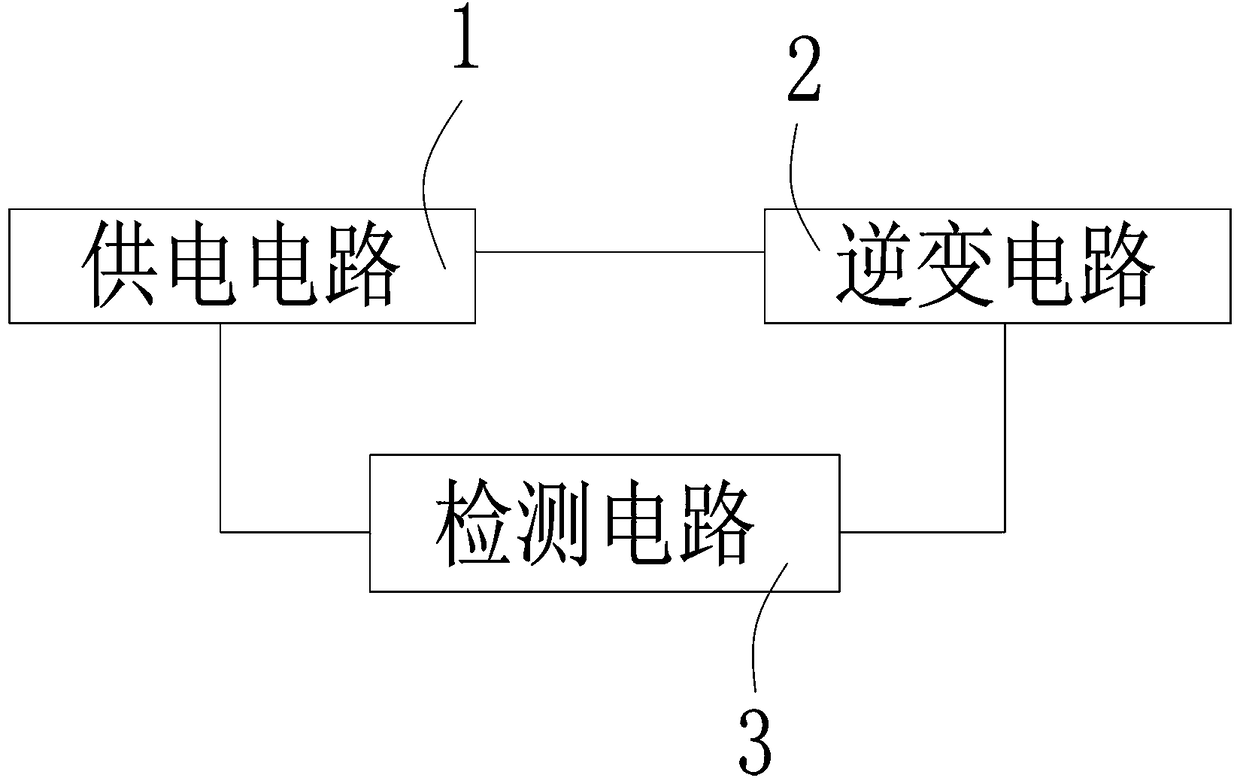
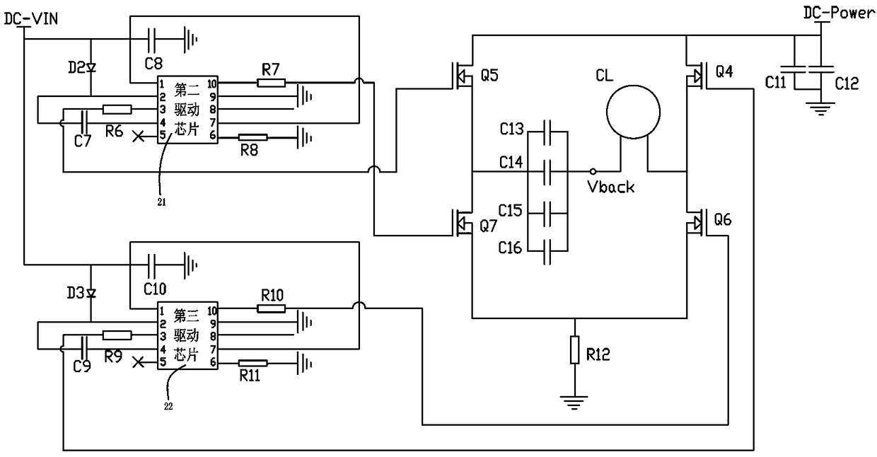
The invention relates to a method and circuit of determining wireless charging foreign matter based on a Q value. The circuit of determining wireless charging foreign matter based on a Q value includes a wireless transmitting circuit and a detection circuit, wherein the detection circuit is electrically connected with the wireless transmitting circuit; the wireless transmitting circuit emits electromagnetic wave which continuously changes the frequency and enables the wireless transmitting circuit to stop working; and during the process of transmitting the electromagnetic wave from the wireless transmitting circuit, the detection circuit detects the Q value of the wireless transmitting circuit, and according to the detected Q value, determines whether foreign matter exists in the electromagnetic wave transmission range of the wireless transmitting circuit. In the circuit of determining wireless charging foreign matter based on a Q value, the wireless transmitting circuit and the detection circuit are employed; the wireless transmitting circuit emits the electromagnetic wave which continuously changes the frequency and enables the wireless transmitting circuit to stop working; and during the process of transmitting the electromagnetic wave from the wireless transmitting circuit, the detection circuit detects the Q value of the wireless transmitting circuit, and according to thedetected Q value, determines whether foreign matter exists in the electromagnetic wave transmission range of the wireless transmitting circuit. The circuit of determining wireless charging foreign matter based on a Q value has the advantages of being simple in the circuit structure, being low in cost and having no influence on the working efficiency of the system.

Description

technical field [0001] The present invention relates to the technical field of wireless charging foreign object detection, in particular to a method and a circuit thereof for judging wireless charging foreign objects based on a Q value. Background technique [0002] Wireless charging technology has been greatly developed in recent years, and has been applied in various electronic devices, especially in consumer electronics such as mobile phones and has become an emerging hot application. However, the detection of metal foreign objects has always been a problem that needs to be improved. In the early days, the energy loss method was mostly used, but the energy loss method will be affected by factors such as the efficiency of the receiving device itself, the distance between the transmitting coil and the receiving coil, and the bias. It's hard to get very high. [0003] Since the wireless charging / power supply device itself is composed of an RLC oscillating circuit, the RLC c...

Claims


Application Information

Patent Timeline
Patent Type & Authority Applications(China)
IPC IPC(8): H02J50/60H02J50/20H02J50/12
CPCH02J50/12H02J50/20H02J50/60
Inventor 邵礼斌
Owner SHENZHEN CHIPSVISION MICRO CO LTD
Learn More