
A Dual Phase Center Altimetry Frequency Scanning Antenna

A frequency scanning antenna, dual-phase technology, applied in the direction of antenna support/installation device, radiating element structure, etc., can solve the problem of inability to achieve dual-phase center frequency scanning antenna elevation angle measurement and so on

Active Publication Date: 2019-10-25
ANHUI SUN CREATE ELECTRONICS
View PDF7 Cites 0 Cited by
  • Summary
  • Abstract
  • Description
  • Claims
  • Application Information

AI Technical Summary

Problems solved by technology

[0004] At present, the simplest method is to use the composition principle of a single-baseline phase interferometer and use a single-phase central antenna to form a dual-phase central antenna, but the two single-phase central antennas cannot achieve a dual-phase central frequency The Function of Measuring the Angle of Elevation Plane of Scanning Antenna

Method used


Image

  • A Dual Phase Center Altimetry Frequency Scanning Antenna
  • A Dual Phase Center Altimetry Frequency Scanning Antenna
  • A Dual Phase Center Altimetry Frequency Scanning Antenna

Examples


Embodiment 1

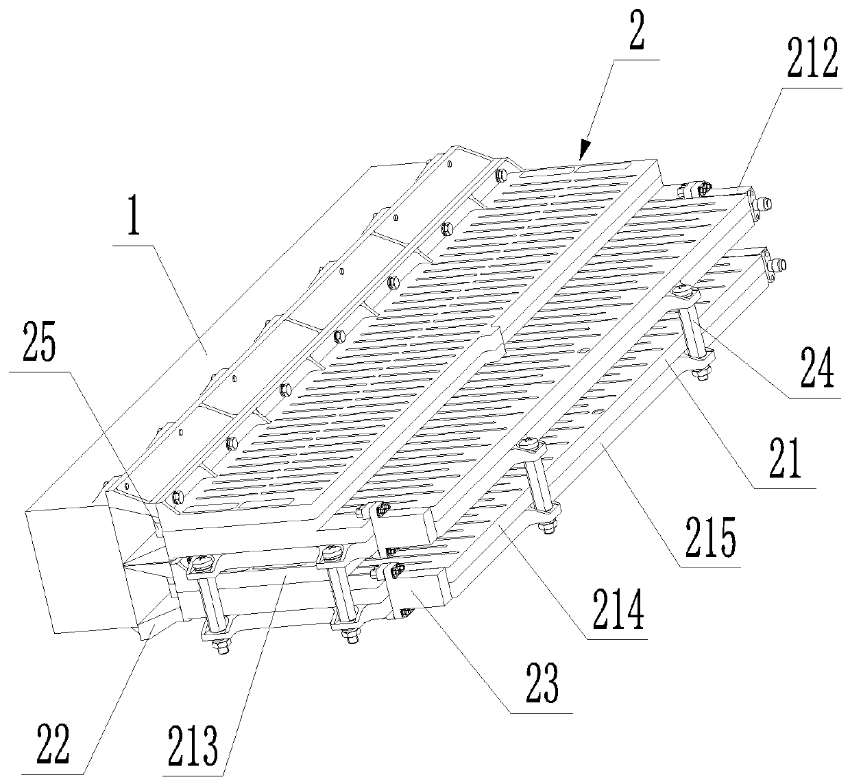
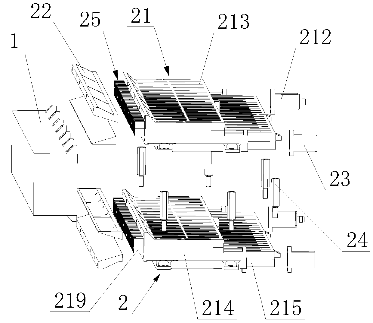
[0053] Such as Figure 7 As shown, this embodiment provides a dual-phase central altimetry frequency scanning antenna, the working frequency range is 15.7GHz to 17.2GHz, the slow wave line cavity adopts the form of a rectangular waveguide serpentine line, and the straight waveguide cavity adopts the standard BJ180 model. The aperture size of the hole is 12.95×6.48mm, and the distance between adjacent couplers 25 is 10.2mm. According to the actual aperture size distribution and gain requirements, there are 42 couplers 25 in total, and the Taylor weighting is carried out according to -29dB. At a center frequency of 16.45 GHz, the slow wave line transmits 4.5 wavelengths between adjacent couplers 25 . Such as Figure 7 As shown, the distance d=32mm between the two receiving antennas 2, the aperture Tc=30mm of the wing plate 22, and the angle a=16.8° between the coupler, the width Hk=62mm of the dielectric block 1, and its height Hd=45mm.

[0054] The distance between the two r...


PUM


Abstract

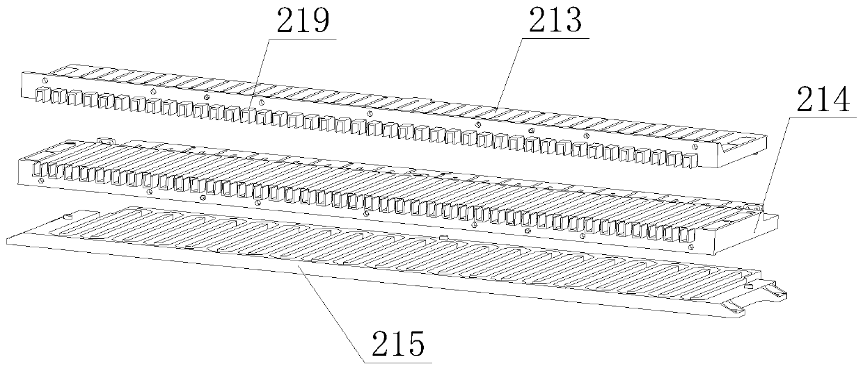
The invention belongs to the technical field of antennas, and particularly relates to a dual-phase center height-measurement frequency scanning antenna. The dual-phase center height-measurement frequency scanning antenna comprises a dielectric block and two same-structure receiving antennas, wherein the two receiving antennas are fixedly connected, the dielectric block is fixedly connected with the two receiving antennas, each receiving antenna comprises a slow wave line assembly and two wing plates, a receiving hole is formed in an inlet of a straight waveguide cavity of the slow wave line assembly, the two wing plates are respectively arranged at two sides of the receiving hole, a waveguide converter is arranged at one end part of the slow wave line cavity of the slow wave line assembly,the two receiving antennas are vertically arranged in parallel, the slow wave line assemblies of the two receiving antennas are fixedly connected, and the dielectric block is fixedly arranged on thewing plates of the two receiving antennas. By the antenna, a relatively large pitching measurement angle range is achieved on the premise of no influence on the working performance of a single-phase central frequency scanning antenna, and the pitching measurement demand of actual engineering application is satisfied.

Description

technical field [0001] The invention belongs to the technical field of antennas, and in particular relates to a dual-phase central altimetry frequency scanning antenna. Background technique [0002] The frequency scanning antenna has the advantages of high gain, low sidelobe, wide-angle scanning, low cost, and simple structure. , coupling feed structure, and radiating antenna are composed of three parts, including the combination of microstrip slow wave line and microstrip radiating antenna, the combination of stripline slow wave line and dipole radiating antenna, the combination of waveguide slow wave line and microstrip radiating antenna, etc. Select the appropriate frequency scanning antenna form according to actual needs. [0003] The single-phase center frequency scanning antenna can complete the beam scanning in the azimuth direction, and determine the incoming wave direction of the target in the azimuth direction, but the elevation direction cannot be measured. Howe...

Claims


Application Information

Patent Timeline
Patent Type & Authority Patents(China)
IPC IPC(8): H01Q1/12H01Q1/36
CPCH01Q1/12H01Q1/36
Inventor 赵继明胡卫东禹清晨孙浩
Owner ANHUI SUN CREATE ELECTRONICS
Learn More