
Mechanism used for separating product from fixed mould and capable of limiting slide block by adopting perpendicular locking surface for fixed mould and deep rib

A technology of fixed mold and slider, applied in the field of mold release mechanism, can solve the problems of unfavorable maintenance and maintenance, complex elastic block structure, low yield and other problems, and achieve the effects of simple structure, low cost and high yield

Active Publication Date: 2018-06-15
NINGBO FANGZHENG TOOL
View PDF3 Cites 0 Cited by
  • Summary
  • Abstract
  • Description
  • Claims
  • Application Information

AI Technical Summary

Problems solved by technology

[0002] When the deep ribs of the product (generally, the height of the ribs is more than 1cm higher than the surface) is located on the fixed mold, the product tends to stay on the fixed mold when the mold is opened. The mold is disengaged, but in the actual production process, due to the influence of mold temperature and precision, it is often not easy for the spring block to disengage the product from the fixed mold in time, resulting in damage to the product or the final product falling off. Under the action of the spring, it is easy to leave marks on the product, the yield rate is relatively low, and the structure of the bullet block is more complicated, which is not conducive to subsequent maintenance and maintenance

Method used


Image

  • Mechanism used for separating product from fixed mould and capable of limiting slide block by adopting perpendicular locking surface for fixed mould and deep rib
  • Mechanism used for separating product from fixed mould and capable of limiting slide block by adopting perpendicular locking surface for fixed mould and deep rib
  • Mechanism used for separating product from fixed mould and capable of limiting slide block by adopting perpendicular locking surface for fixed mould and deep rib

Examples


Embodiment Construction

[0023] The present invention will be further described below in conjunction with the accompanying drawings and specific embodiments.

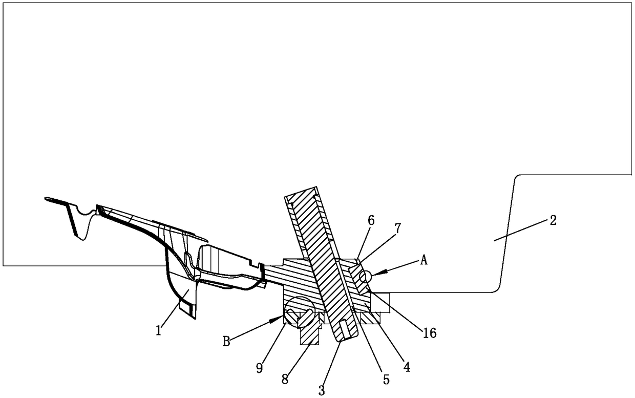
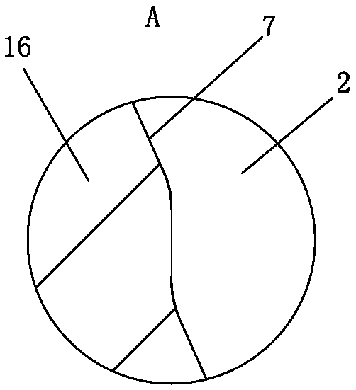
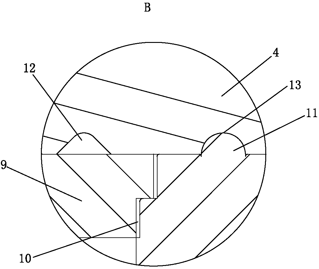
[0024] Such as Figure 1-7 As shown, the present invention provides a product fixed mold deep rib slider facing directly to lock and disengage from the fixed mold mechanism, which includes a cavity 1, an inclined guide post 3 arranged on the fixed mold 2 and a slide block slidably arranged on the movable mold 4. The end surface of the slider 4 near the cavity 1 is a deep rib corresponding to the side wall of the cavity 1, that is to say, the end surface of the slider 4 near the cavity 1 forms the cavity 1 together with the fixed mold 2 and the movable mold. The end face of the slider 4 near the cavity 1 is a part of the side wall corresponding to the deep rib, and is located above the product edge corresponding to the cavity 1. The value after subtracting 1.0 to 3.5mm from the height (2.5mm in this example, can also be 1.0mm, 2.0mm, 3.0mm or 3...


PUM

PropertyMeasurementUnit
Lengthaaaaaaaaaa

Abstract

The invention discloses a mechanism used for separating a product from a fixed mould and capable of limiting a slide block by adopting a perpendicular locking surface for the fixed mould and a deep rib. The mechanism comprises a mould cavity (1), an inclined guide post (3) arranged on the fixed mould (2) and the slide block (4) which is arranged on a movable mould in a sliding mode, wherein one end, close to the mould cavity (1), of the slide block (4) is a side wall, which corresponds to the mould cavity (1), of the deep rib, and is positioned above a position, which corresponds to the mouldcavity (1), of a product edge; height of one end, close to the mould cavity (1), of the slide block (4) is a value obtained by subtracting 1.0-3.5mm from height of the deep rib; a stroke limiting mechanism is arranged between the slide block (4) and the movable mould; an inclined hole (5) which is in sliding fit to the inclined guide post (3) is formed in the slide block (4); the inclined hole (5)is greater than the outer diameter of the inclined guide post (3); one end, away from the mould cavity (1), of the slide block is equipped with an inclined surface (6); and a pressing surface (7) which presses the slide block (4) when the pressing surface is matched with the inclined surface (6) for closing the mould is arranged on the fixed mould (2). Compared with the prior art, the mechanism has characteristics of being simple in structure, convenient to maintain and repair, and capable of increasing the product yield.

Description

technical field [0001] The invention relates to a demoulding mechanism of a mould, in particular to a product fixed mold deep rib slider facing directly to lock and release the fixed mold mechanism. Background technique [0002] When the deep ribs of the product (generally, the height of the ribs is more than 1cm higher than the surface) is located on the fixed mold, the product tends to stay on the fixed mold when the mold is opened. The mold is disengaged, but in the actual production process, due to the influence of mold temperature and precision, it is often not easy for the spring block to disengage the product from the fixed mold in time, resulting in damage to the product or the final product falling off. Under the action of the spring, it is easy to leave traces on the product, the yield rate is relatively low, and the structure of the spring block is relatively complicated, which is not conducive to subsequent maintenance and maintenance. Contents of the invention...

Claims


Application Information

Patent Timeline
IPC IPC(8): B29C33/76B29C45/33
CPCB29C33/76B29C45/332
Inventor 金欢屠立斌吴行盛王永盛郑立剑周诗王林明
Owner NINGBO FANGZHENG TOOL
Learn More