
Silicon-based OLED displayer module and its preparation method

A display and silicon-based technology, which is applied in the field of silicon-based OLED display modules and their preparation, can solve the problems of improving the preparation difficulty of silicon-based OLED display modules, unfavorable miniaturization of silicon-based OLED display modules, and increasing requirements. , to achieve the effect of improving the typesetting rate, reducing the size, and reducing the preparation accuracy

Inactive Publication Date: 2018-06-12
KUNSHAN FANTAVIEW ELECTRONICS TECH CO LTD
View PDF8 Cites 11 Cited by
  • Summary
  • Abstract
  • Description
  • Claims
  • Application Information

AI Technical Summary

Problems solved by technology

[0004] In the prior art, the metal leads are often arranged on the surface of the silicon-based backplane, so when making the OLED layer and the thin film encapsulation layer on the silicon-based backplane, it is necessary to use a metal mask to cover the bonding area of ​​the metal leads to prevent the formation of the OLED layer. And the material of the thin film encapsulation layer is formed into a film in the Bonding area. However, with the continuous development of encapsulation technology, the OLED layer and the thin film encapsulation layer have higher and higher requirements for the setting of the metal mask in the preparation process layer. The shadow area needs to be controlled within 1mm, which greatly increases the difficulty of manufacturing silicon-based OLED display modules
At the same time, the metal leads will occupy the preparation area of ​​the OLED layer on the silicon-based backplane, resulting in a relatively large size of the silicon-based OLED display module in the prior art, which is not conducive to the miniaturization of the silicon-based OLED display module

Method used


Image

  • Silicon-based OLED displayer module and its preparation method
  • Silicon-based OLED displayer module and its preparation method

Examples


Embodiment Construction

[0028] In order to make the object, technical solution and advantages of the present invention clearer, the present invention will be described in detail below in conjunction with the accompanying drawings and specific embodiments.

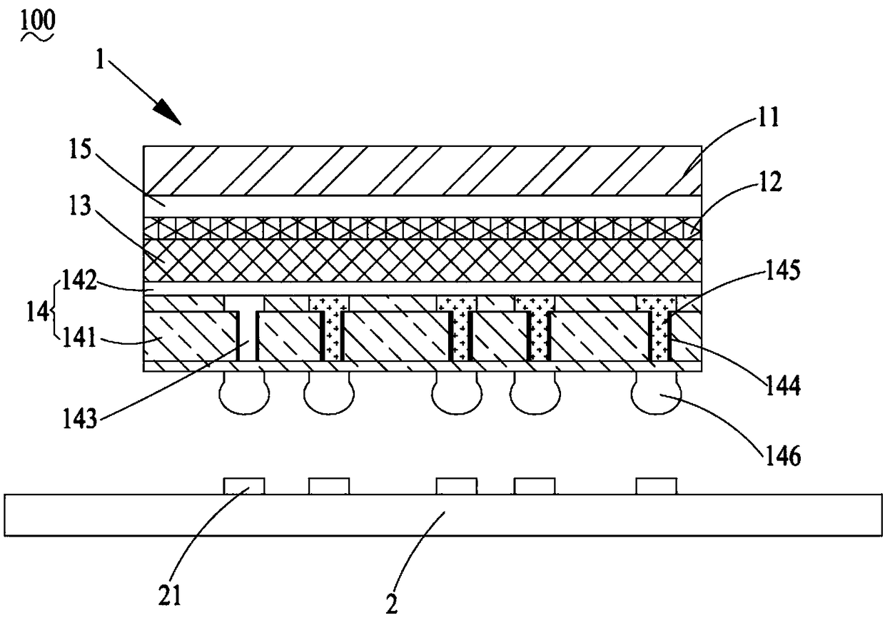
[0029] see figure 1 As shown, a silicon-based OLED display module 100 provided by the present invention includes a silicon-based OLED module 1 and a PCB board 2 electrically connected to the silicon-based OLED module 1 .

[0030] The silicon-based OLED module 1 includes a transparent encapsulation layer 11, a thin-film encapsulation layer 12, an OLED light-emitting layer 13, and a silicon-based backplane 14 arranged sequentially from top to bottom. Further, the transparent encapsulation layer 11 and the A color filter 15 is disposed between the thin film encapsulation layers 12 .

[0031] In the embodiment of the present invention, the transparent encapsulation layer 11 is a transparent glass encapsulation layer, further, the transparent glass en...


PUM

PropertyMeasurementUnit
Hole lengthaaaaaaaaaa
Apertureaaaaaaaaaa

Abstract

The invention provides a silicon-based OLED displayer module, which comprises a silicon-based OLED module and a PCB board electrically connected with the silicon-based OLED module; the silicon-based OLED module comprises a transparent packaging layer, a thin film packaging layer, an LED lighting layer and a silicon-based back plate which are orderly distributed from top to bottom; the silicon-based back plate comprises a back plate main body and a driving electrode layer arranged between the OLED lighting layer and the back plate main body; conductive through holes aligned regularly are arranged on the back plate main body, insulation layers are deposited on the surfaces of the conductive through holes, and conductive pillars are arranged in the conductive through holes. The silicon-basedOLED displayer module cancels the Bonding zone of the silicon-based back plate, reduces the dimension of the silicon-based OLED displayer module, improves the composing rate, and further reduces the preparation cost of the silicon-based OLED displayer module.

Description

technical field [0001] The invention relates to a silicon-based OLED display module and a preparation method thereof, belonging to the field of OLED display manufacture. Background technique [0002] Compared with CTR (CathodeRay Tube, cathode ray tube) display or TFT-LCD (Thin Film Transistor-Liquid Crystal Display, thin film transistor liquid crystal display), OLED (Organic Light-Emitting Diode) display has lighter and thinner With features such as appearance design, wider viewing angle, faster response speed, and lower power consumption, OLED displays have gradually attracted people's attention as a next-generation display device. [0003] In the prior art, the conventional preparation method of a silicon-based OLED display module is: preparing an OLED device on a silicon-based backplane integrated with circuits; then, encapsulating the OLED device with a thin film; finally, using a transparent cover plate to encapsulate the thin film. Parallel encapsulation of the OLED ...

Claims


Application Information

Patent Timeline
IPC IPC(8): H01L27/32
CPCH10K59/12
Inventor 吴疆
Owner KUNSHAN FANTAVIEW ELECTRONICS TECH CO LTD
Learn More