
paper cutter

A paper cutter and cutting mechanism technology, applied in metal processing, etc., can solve the problems of cumbersome operation, low efficiency, and low degree of automation, and achieve the effect of simplifying operation steps and improving efficiency

Active Publication Date: 2019-06-28
浙江拉菲草纸制品有限公司
View PDF3 Cites 0 Cited by
  • Summary
  • Abstract
  • Description
  • Claims
  • Application Information

AI Technical Summary

Problems solved by technology

[0003] A paper cutter is needed to cut paper. In order to improve efficiency, most of the paper cutters on the market, when cutting paper, the paper conveyor belt is running continuously instead of pausing, even if the cutting speed of the paper cutter is very fast. Fast, it is easy to produce burrs at the incision of the paper, which affects the quality of the product
Moreover, the existing paper cutters are not highly automated. After the paper is cut into sheets, workers need to collect the cut paper and stack the paper. The whole process is cumbersome and inefficient.

Method used


Image

  • paper cutter
  • paper cutter

Examples


Embodiment Construction

[0019] The present invention will be described in further detail below by means of specific embodiments:

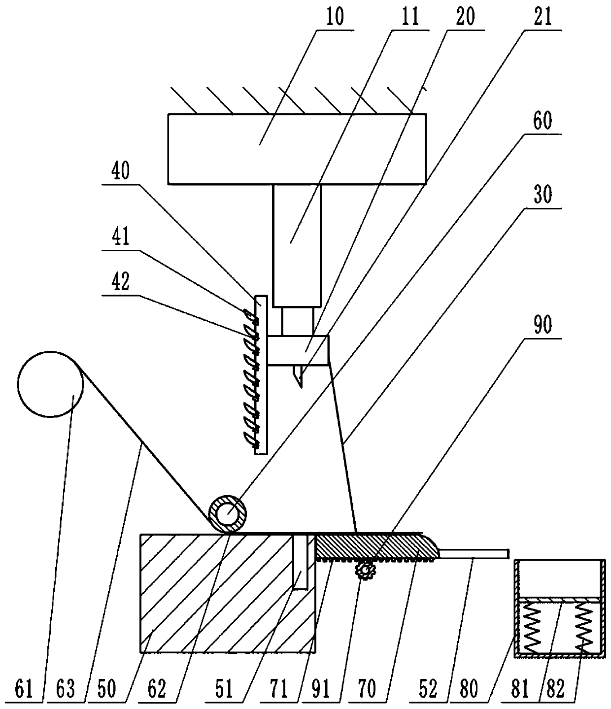
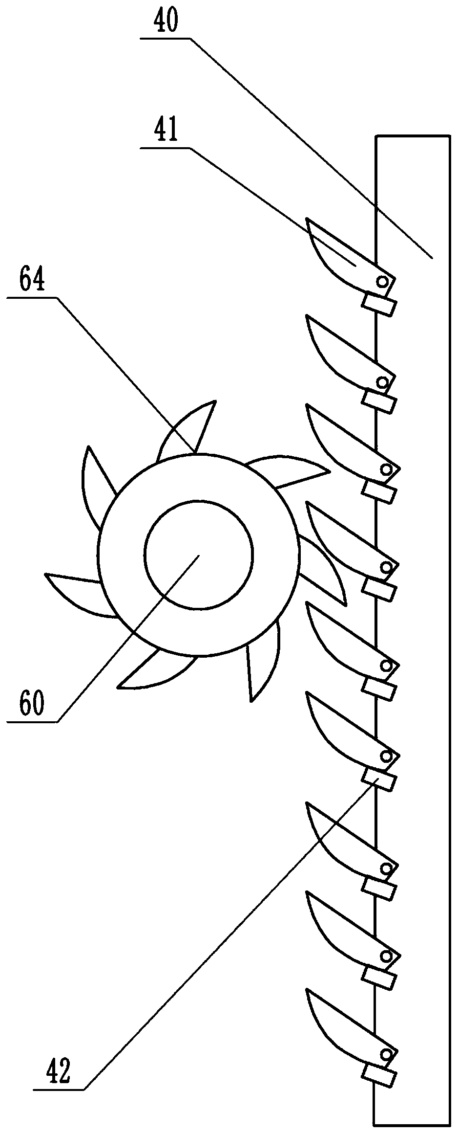
[0020] Instructions attached figure 1 The reference signs in include: frame 10, hydraulic cylinder 11, mounting seat 20, cutting knife 21, pull cord 30, mounting bar 40, claw 41, block 42, workbench 50, cutting groove 51, slide rail 52 , Rotating shaft 60, paper feed roller 61, unwinding roller 62, paper 63, ratchet 64, transmission plate 70, rack 71, collection tank 80, support plate 81, spring 82, transmission shaft 90, gear 91.

[0021] like figure 1 As shown, the paper cutter includes a paper feeding mechanism, a cutting mechanism and a collecting mechanism for collecting the cut paper 63 . The cutting mechanism includes a workbench 50, a frame 10, a mounting seat 20 and a power unit installed on the frame 10. In this embodiment, the power unit is a hydraulic cylinder 11, and the mounting seat 20 is fixed on the piston rod of the hydraulic cylinder 11. Mounting str...


PUM


Abstract

The invention belongs to the field of paper processing devices, and particularly discloses a paper cutting machine. The paper cutting machine comprises a paper feeding mechanism, a cutting mechanism and a collection mechanism, wherein the cutting mechanism comprises a workbench, a rack, a mounting base, a cutter and a power device; a cutting groove is formed in the upper surface of the workbench;the paper feeding unit comprises an uncoiling roller, a rotary shaft and a paper feeding roller; the paper feeding roller is fixed to the rotary shaft; the rotary shaft is provided with a ratchet wheel; the mounting base is provided with a mounting strip; a plurality of clamping jaws are hinged to the mounting strip and can be clamped to the ratchet wheel; the collection mechanism comprises a slide rail, a torsional spring, a transmission shaft, a conveying board and a collection tank; the conveying board is in sliding connection with the slide rail; a gear is fixed to the transmission shaft;a rack is arranged on the lower surface of the conveying board; one end of the torsional spring is fixed to the workbench; the other end of the torsional spring is fixed to the transmission shaft; thetransmission shaft is wound with a pull rope; and the pull rope is connected to the mounting base. When the paper cutting machine is used, the cutting quality can be ensured, burrs at notches are avoided, cut paper can be effectively collected, and pieces of paper are stacked orderly.

Description

technical field [0001] The invention belongs to the technical field of paper processing devices, and in particular relates to a paper cutter. Background technique [0002] The paper purchased from the paper mill is usually in rolls, and the paper is wound on the unwinding roller. In the printing and processing industry, when using these papers, the paper needs to be cut to a suitable size before printing and processing. [0003] A paper cutter is needed when cutting paper. In order to improve efficiency, most of the paper cutters on the market now have the paper conveyor belt running continuously instead of pausing, even if the cutting speed of the paper cutter is very fast. Quickly, it is easy to produce burrs at the incision of the paper, which affects the quality of the product. Moreover, the existing paper cutters are not highly automated. After the paper is cut one by one, workers need to collect the cut paper and stack the paper. The whole process is cumbersome and in...

Claims


Application Information

Patent Timeline
Patent Type & Authority Patents(China)
IPC IPC(8): B26D1/06B26D7/32B26D5/12
CPCB26D1/065B26D5/12B26D7/32B26D2007/322
Inventor 胡荣生
Owner 浙江拉菲草纸制品有限公司
Learn More