
Automatic irrigator for flowerpots

An automatic watering and flowerpot technology, applied in automatic watering devices, chemical instruments and methods, chemical/physical/physical-chemical stationary reactors, etc. Occupancy, easy access, cost reduction effect

Inactive Publication Date: 2018-06-12
郭雨耕
View PDF8 Cites 3 Cited by
  • Summary
  • Abstract
  • Description
  • Claims
  • Application Information

AI Technical Summary

Problems solved by technology

This method needs to install or hang the water supply device on one side of the flower pot, which takes up space and is not beautiful enough

Method used


Image

  • Automatic irrigator for flowerpots

Examples


Embodiment Construction

[0020] The following will clearly and completely describe the technical solutions in the embodiments of the present invention with reference to the accompanying drawings in the embodiments of the present invention. Obviously, the described embodiments are only some, not all, embodiments of the present invention. Based on the embodiments of the present invention, all other embodiments obtained by persons of ordinary skill in the art without making creative efforts belong to the protection scope of the present invention.

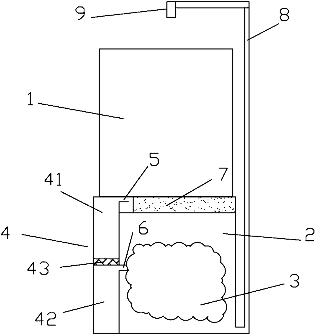
[0021] like figure 1 As shown, the present invention provides an automatic watering device for flower pots, comprising a water container 2, a deformable gas collector 3 and a gas generator 4; the deformable gas collector 3 is arranged in the water container 2; the gas generator 4 includes an upper layer 41 of the gas generator and a lower layer 42 of the gas generator. The upper layer 41 of the gas generator and the lower layer 42 of the gas generator are sepa...


PUM


Abstract

The invention discloses an automatic irrigator for flowerpots, comprising a water container, a deformable gas collector and a gas generator; the deformable gas collector is arranged in the water container; the gas generator comprises a gas generator upper layer and a gas generator lower layer; the gas generator upper layer and the gas generator lower layer are spaced via a partition; the partitionis made of a material that is high in water permeability and poor in breathability; the gas generator lower layer is communicated with the deformable gas collector through a gas guide tube; the watercontainer is communicated with a compensating irrigator through a water supply pipe. Gas generated by reaction in the gas generator is used as irrigating power; potted plants can be automatically irrigated with no assistance from a power system.

Description

technical field [0001] The invention relates to the technical field of vegetation watering, in particular to an automatic watering device for flower pots. Background technique [0002] Now more and more people like to plant potted plants on balconies or roofs, but the automatic irrigation of potted plants is still a headache for people. In order to realize the automatic irrigation of potted plants, existing technical means are (1) pump water, utilize micro-pump water to irrigate, adopt timed water supply or measure flower pot soil moisture content or soil water potential by sensor, start irrigation automatically. However, it has the disadvantages of complex equipment, high cost, and the need for power supply. (2) Use the water potential difference to absorb water from the bottom. When the soil is dry, the soil water potential drops, and the porous medium is used to absorb water from the water reservoir at the bottom of the flower pot, and the flower pot is placed in water....

Claims


Application Information

Patent Timeline
IPC IPC(8): A01G27/02A01G27/00B01J19/00B01J19/24B01J4/00C01B32/50
CPCA01G27/003A01G27/02B01J4/001B01J19/00B01J19/0053B01J19/24B01J2204/002B01J2204/005Y02P20/141
Inventor 郭雨耕
Owner 郭雨耕
Learn More