A support platform for architectural decoration

A technology of architectural decoration and support platform, which is applied in the direction of construction, building structure, and housing structure support, etc., which can solve problems such as accidental damage, long ladders, and inconvenient transportation, and achieve the effect of convenient transportation

Active Publication Date: 2019-12-03
青岛西海岸城市建设集团有限公司
View PDF4 Cites 0 Cited by
  • Summary
  • Abstract
  • Description
  • Claims
  • Application Information

AI Technical Summary

Problems solved by technology

When faced with houses of different heights, decoration workers need to set up ladders to assist in their work, but ordinary ladders are convenient to set up, but they are not safe, and they are prone to accidental damage, and the ladders are long and inconvenient to carry, so this kind of building was designed decorative stand

Method used


Image

  • A support platform for architectural decoration
  • A support platform for architectural decoration
  • A support platform for architectural decoration

Examples


specific Embodiment approach 1

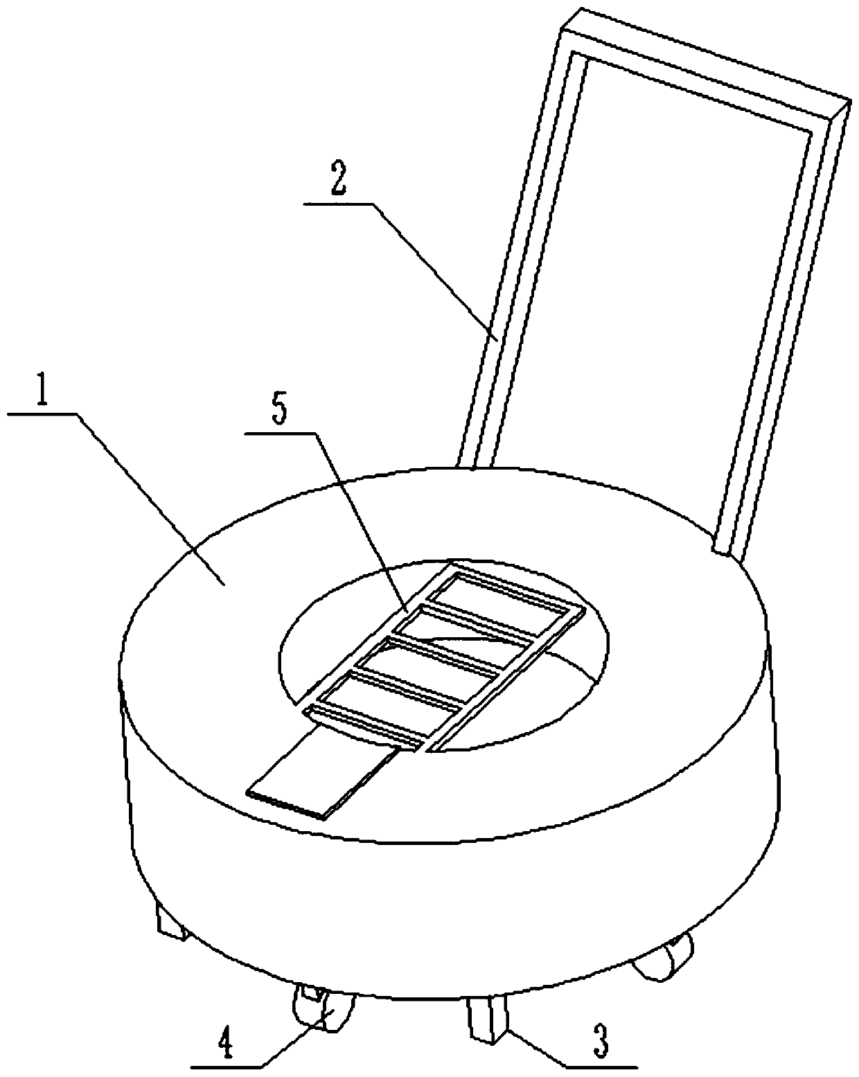
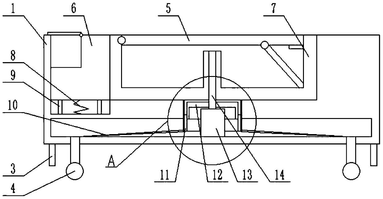
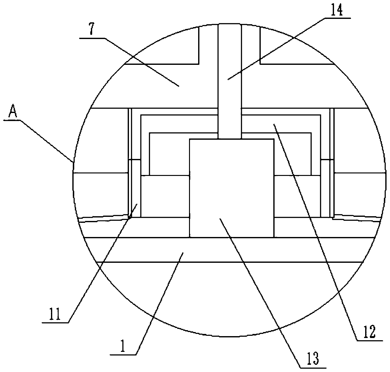
[0030] Combine below figure 1 , 2 , 3, 4, 5, 6, 7, 8, 9, and 10 illustrate this embodiment. The present invention relates to a tool for architectural decoration, more specifically a support platform for architectural decoration, including a round platform 1, a push handle 2 , bracket 3, wheel 4, ladder 5, auxiliary ladder 6, rotating device 7, spring 8, support ring 9, connecting rod 10, ring 11, transmission ring 12, motor 13, shaft 14, not only convenient to carry, but also The height of the ladder can be adjusted during use, making it convenient to work indoors at different heights.

[0031] The round table 1 is composed of a round table main body 1-1, groove I1-2, groove II1-3, groove III1-4, through hole 1-5, chute 1-6, and groove IV1-7; the round table main body 1- 1 The bottom end is provided with a through hole 1-5; the groove III 1-4 is arranged inside the main body 1-1 of the round platform, and the groove III 1-4 communicates with the through hole 1-5; the groove ...

specific Embodiment approach 2

[0039] Combine below figure 1 , 2 , 3, 4, 5, 6, 7, 8, 9, and 10 illustrate this embodiment, and this embodiment further describes Embodiment 1, and there are multiple vertical bars II 5-5.

specific Embodiment approach 3

[0041] Combine below figure 1 , 2 , 3, 4, 5, 6, 7, 8, 9, and 10 illustrate this embodiment. This embodiment will further describe Embodiment 1. When the vertical rod II 5-5 is connected with the vertical rod I 5-1 by bolts, the telescopic The rods 5-3 are supported at the corners of the grooves 7-2.


PUM


Abstract

The invention relates to a tool for building decoration, in particularly to a supporting platform for building decoration. Not only is the supporting platform convenient to carry, but also the heightof a ladder can be adjusted when the supporting platform is used, so that the supporting platform is convenient to work in rooms different in height. Sliding strips are in clearance fit with sliding grooves, one ends of connecting rods are fixedly connected to the lower end of a ring main body by welding, and the other ends of the connecting rods are fixedly connected to supporting rods at the upper ends of wheels by welding. Vertical rods I on the ladder are movably connected to rotating discs through hinges, vertical rods II on the ladder are placed at the upper end of an upper baffle, the lower ends of supporting rings are fixedly connected to the bottom end of a groove I by welding, and a boss I is placed at the upper ends of the supporting rings. A boss II is placed at the upper endsof the supporting rings, the lower end of a spring is fixedly connected to the bottom end of the groove I by welding, the upper end of the spring is fixedly connected to the lower end of an auxiliaryladder by welding, a baffle is placed at the upper end of a round table, and a push rod is fixedly connected to the round table by welding.

Description

technical field [0001] The invention relates to a tool for architectural decoration, in particular to a support platform for architectural decoration. Background technique [0002] With the improvement of people's appreciation of the interior, different types of interior layout houses are displayed in front of the public, and the interior heights are also different. When faced with houses of different heights, decoration workers need to set up ladders to assist in their work, but ordinary ladders are convenient to set up, but they are not safe, and they are prone to accidental damage, and the ladders are long and inconvenient to carry, so this kind of building was designed Stand for decoration. Contents of the invention [0003] The invention provides a support platform for architectural decoration, which has the beneficial effects of being convenient for transportation and being able to adjust the height of the ladder during use, so as to facilitate indoor work at differ...

Claims


Application Information

Patent Timeline
Patent Type & Authority Patents(China)
IPC IPC(8): E04G1/22E04G1/24
CPCE04G1/22E04G1/24E04G2001/246
Inventor 姜敏敏
Owner 青岛西海岸城市建设集团有限公司
Why Eureka
Try Eureka