
Programmable Gain Amplifier

A technology of gain amplifiers and transistors, applied in amplifiers, differential amplifiers, DC-coupled DC amplifiers, etc., can solve problems such as inability to effectively isolate noise and reduce the output signal-to-noise ratio of programmable gain amplifiers, so as to avoid noise and reduce The effect of the signal-to-noise ratio

Active Publication Date: 2021-05-25
SILICON INTEGRATED SYSTEMS
View PDF6 Cites 0 Cited by
  • Summary
  • Abstract
  • Description
  • Claims
  • Application Information

AI Technical Summary

Problems solved by technology

Such a structure cannot effectively isolate the noise, so that the noise is amplified by the programmable gain amplifier together with the desired signal, thereby reducing the output signal noise ratio (signal noiseratio, SNR) of the programmable gain amplifier

Method used


Image

  • Programmable Gain Amplifier
  • Programmable Gain Amplifier
  • Programmable Gain Amplifier

Examples


Embodiment Construction

[0041]The detailed features and advantages of the present invention are described in detail below in the embodiments, which are sufficient for any person skilled in the art to understand the technical content of the present invention and implement it. The related objects and advantages of the present invention can be easily understood by those skilled in the art. The following examples further describe the viewpoints of the present invention in detail, but do not limit the protection scope of the present invention in any viewpoint.

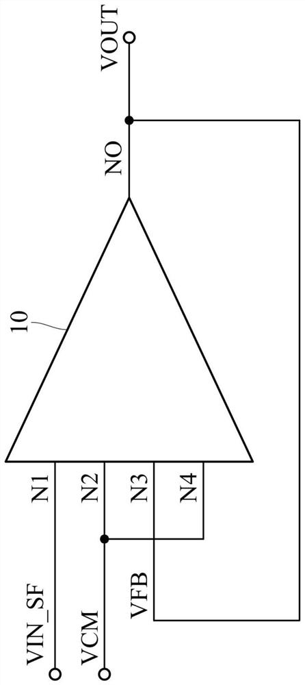
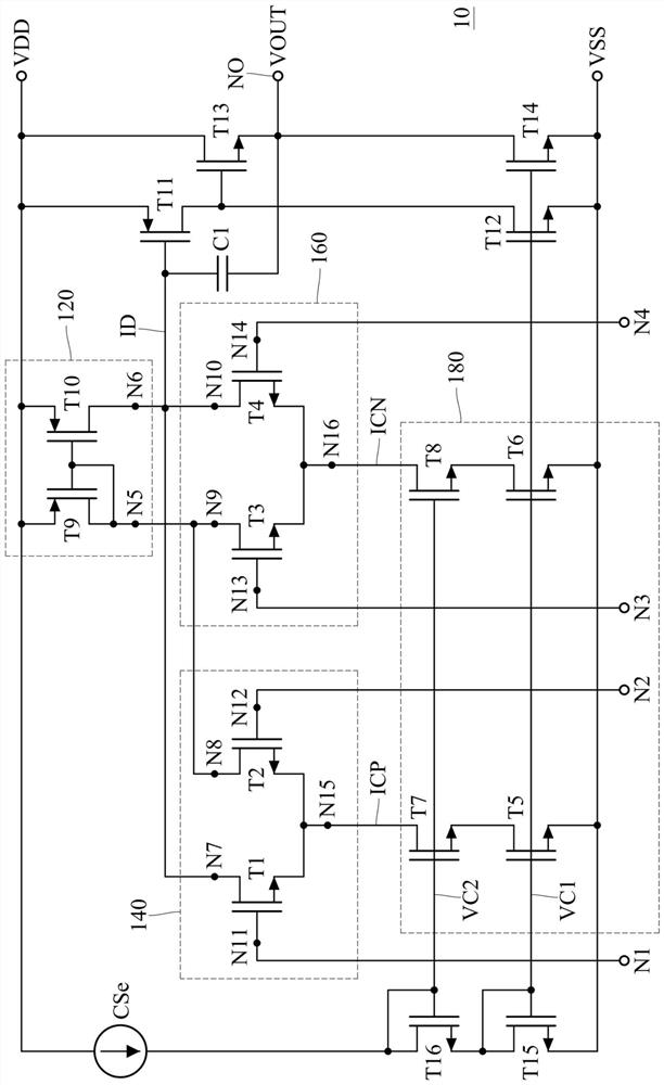
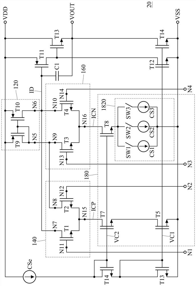
[0042] figure 1 It is an equivalent circuit diagram of a programmable gain amplifier according to an embodiment of the present invention. Please refer to figure 1 The input and output of the programmable gain amplifier provided by the present invention will be described. The programmable gain amplifier 10 provided by the present invention has input terminals N1 - N4 and an output terminal NO. The input terminal N1 is used to receive the input ...


PUM


Abstract

A programmable gain amplifier has an active load module, a first differential pair, a second differential pair and a current source module; the first differential pair and the second differential module are respectively electrically connected to the active load module; the current source module The first current source terminal of the first differential pair is electrically connected with the second current source terminal of the second differential pair; the current source module is used for providing the first current to the first differential pair through the first current source terminal; the current The source module is used for providing the second current to the second differential pair through the second current source terminal; and the current source module is used for adjusting the magnitude of the first current and / or the magnitude of the second current.

Description

technical field [0001] The invention relates to a programmable gain amplifier, in particular to a programmable gain amplifier with a feedback path. Background technique [0002] Generally speaking, in order to meet or effectively use the dynamic range of the back-end circuit, users usually set a programmable gain amplifier (programmable gain amplifier, PGA) between the signal source and the back-end circuit, so that the programmable gain amplifier Selectively amplify the signal source with an adjustable magnification to meet the specifications of the back-end circuit, or to achieve the signal specifications desired by the user. [0003] In the past, most programmable gain amplifiers used operational amplifiers and resistors to form amplifying circuits, such as non-inverting amplifiers. Such a structure cannot effectively isolate the noise, and the noise is amplified by the programmable gain amplifier together with the desired signal, thereby reducing the output signal noise...

Claims


Application Information

Patent Timeline
Patent Type & Authority Patents(China)
IPC IPC(8): H03G1/00H03G3/00H03F3/45
CPCH03F3/45179H03F2203/45012H03G1/0088H03G3/008
Inventor 杨思哲林文琦陈耿男
Owner SILICON INTEGRATED SYSTEMS
Learn More