
Fast locking device

A fast locking and locking rod technology, applied in the direction of the antenna support/installation device, etc., can solve the problems of low reliability, failure to unlock and lock, high position requirements, etc., and achieve wide application range, firm and reliable locking, and rigidity less demanding effect

Active Publication Date: 2018-06-05
CHINA ELECTRONICS TECH GRP CORP NO 14 RES INST
View PDF11 Cites 1 Cited by
  • Summary
  • Abstract
  • Description
  • Claims
  • Application Information

AI Technical Summary

Problems solved by technology

Solve the problem that the two lock hooks have high requirements on the position when fast locking, and when the field of the antenna vehicle is uneven, the unlocking and locking sometimes fail to lock and the reliability is not high.

Method used


Image

  • Fast locking device
  • Fast locking device
  • Fast locking device

Examples


Embodiment Construction

[0039] The present invention will be described in further detail below in conjunction with the accompanying drawings.

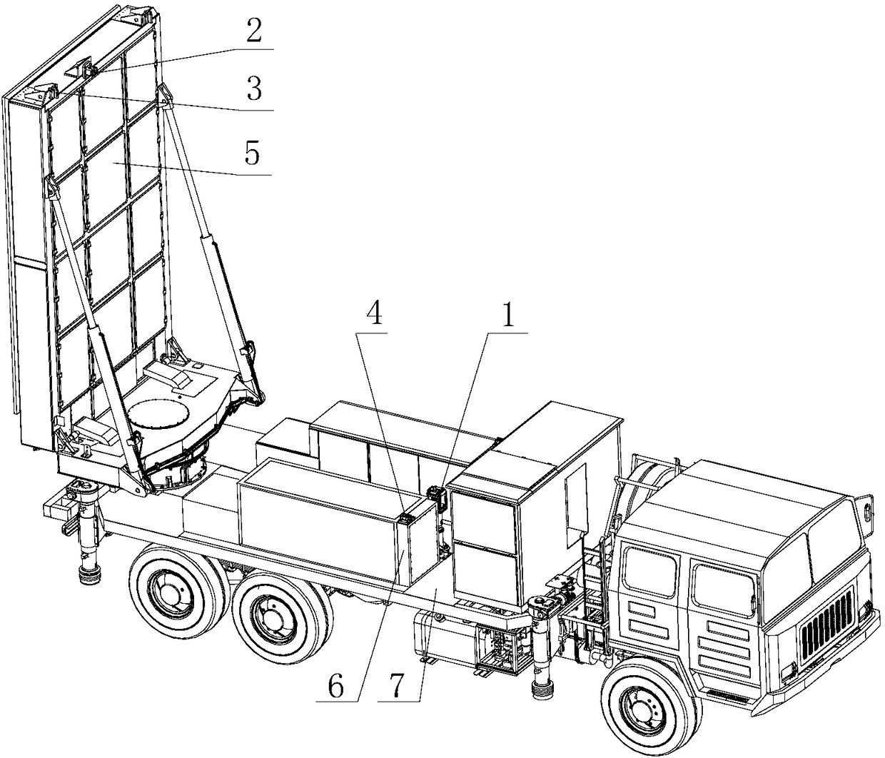
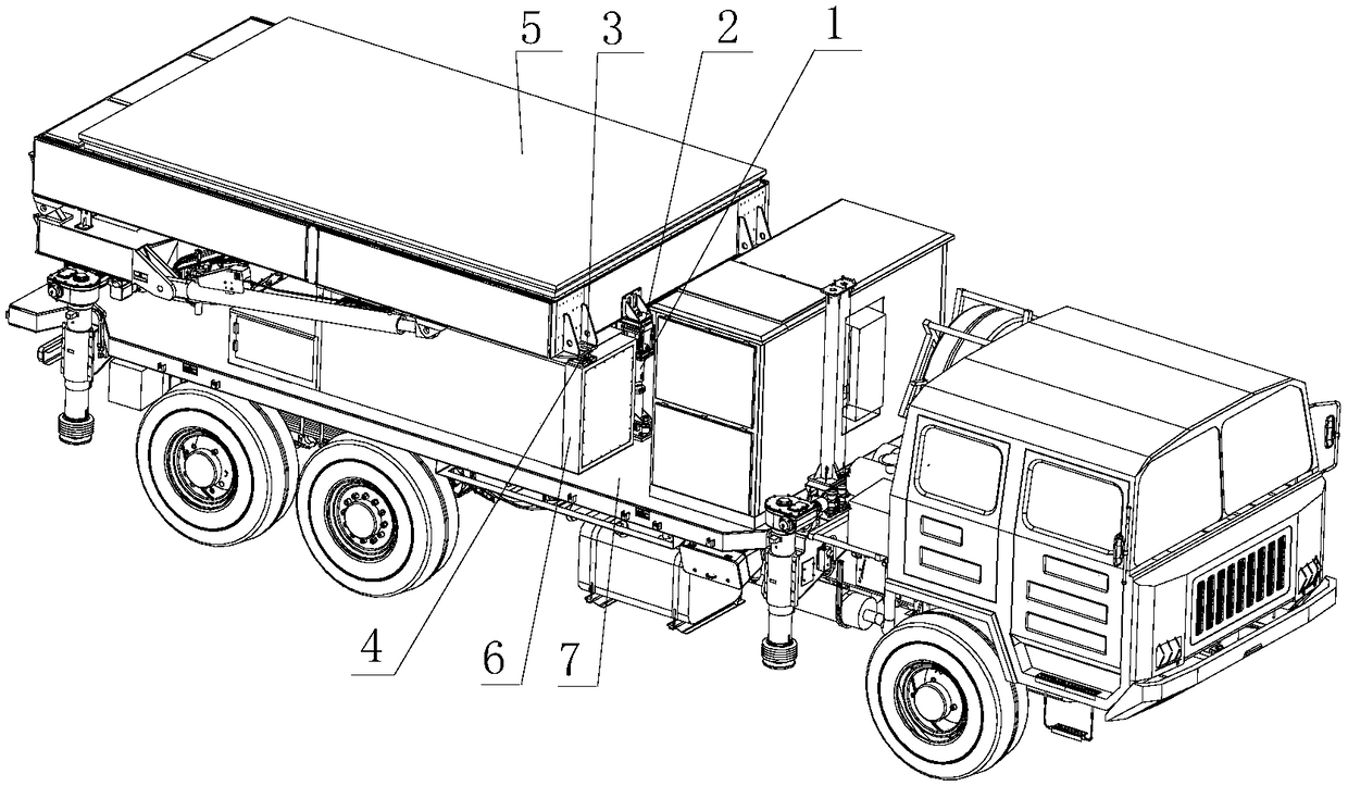
[0040] Such as figure 1 , 2 As shown, the present invention provides a quick locking device, comprising a transport bracket 1 with a locking mechanism, a lock bar 2, a limit block 3, a limit seat 4, the limit seat 4 is installed on the bottom frame 6, and the transport support 1 and the underframe 6 are installed on the car platform 7, and the transport bracket 1 is installed near the center line of the car platform 7; the locking bar 2 and the limit block 3 are installed on the front 5; and the locking bar 2 is installed on the front 5 near the centerline.

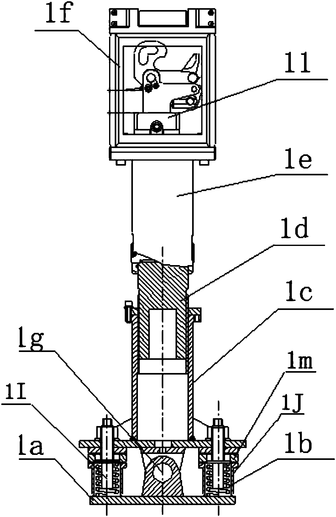
[0041] Such as Figure 3-1 , 3-2 As shown, the transport bracket 1 includes a locking mechanism 11, a frame 1f, a bracket 1e, a base 1a, a spring 1b, a cylinder holder 1c, a shaft cylinder 1d, a thick spring 1k, a pin shaft 1g, an upper pin shaft 1h, and a pole 1I. Sleeve 1J, backing ring 1m; lockin...


PUM


Abstract

The invention discloses a fast locking device, which comprises a transport bracket and a locking rod, wherein the transport bracket is provided with a locking mechanism and installed on a vehicle platform, and the locking rod is installed on an array surface; the transport bracket comprises the locking mechanism, a frame, a support, a base, springs, a cylinder frame, a shaft cylinder, a thick spring, a hinge pin, an upper hinge pin, cylindrical rods and sleeves; the locking mechanism comprises a locking hook, a main hinge pin, a limiting hinge pin, a clamping hook, a torsional spring, a clamping hook hinge pin, a rod hinge pin, a hinge pin, a cylindrical surface, an oil cylinder and a detection device; and the locking rod comprises an installation supporting frame, a support, a locking rodshaft and a locking rod shaft sleeve. The transport bracket locks the locking rod installed on the antenna array surface in a locked manner so as to lock the array surface in all directions. The locking rod shaft sleeve of the locking rod compresses the locking hook of the locking mechanism, the torque of the torsional spring is overcome, and an unlocking state of the locking mechanism is removed; and meanwhile, a spring restoring force in the one-way oil cylinder enables a piston rod to withdraw, and the clamping hook is pulled to lock the locking hook, so that the locking hook locks the locking rod shaft sleeve on the antenna array surface so as to realize locking for the array surface in transportation.

Description

technical field [0001] The invention relates to a quick locking device, in particular to a transport locking device for fronts. Background technique [0002] Existing transport locking devices for antenna arrays often use two-point locking. One is that it can be locked quickly, which requires high position and size, and high leveling accuracy of the vehicle platform. When the position condition is poor and it is quickly disassembled, the locking is easy to make mistakes, and the lock hook cannot be locked, so it needs to be re-leveled Then perform the lock operation. The other kind of locking is not highly automated, semi-automatic and semi-manual, and the locking operation time is 1 minute. All do not meet the needs of high mobility off-road operations. [0003] In the disclosed patent ZL200610120965.X, only the automatic completion of locking (or unlocking) of the moving parts is solved. Contents of the invention [0004] In view of the above problems, the present in...

Claims


Application Information

Patent Timeline
Patent Type & Authority Applications(China)
IPC IPC(8): H01Q1/18
CPCH01Q1/18
Inventor 王雁吴旻丁玉海卜德岭
Owner CHINA ELECTRONICS TECH GRP CORP NO 14 RES INST
Learn More