
Brazing system and working method thereof

A working method and brazing technology, which is applied to welding equipment, manufacturing tools, metal processing equipment, etc., can solve the problems of reducing the service life of vacuum pump units, low service life, and reducing work efficiency, so as to improve heat utilization efficiency and improve use Longevity, the effect of ensuring the quality of brazing

Active Publication Date: 2019-05-17
远大可建科技有限公司
View PDF5 Cites 0 Cited by
  • Summary
  • Abstract
  • Description
  • Claims
  • Application Information

AI Technical Summary

Problems solved by technology

[0002] The existing brazing system mainly has the following defects: (1) The vacuuming speed is slow, and if the vacuuming is too long, the energy consumption of the vacuum pump unit will be greatly increased, and the service life of the vacuum pump unit will be reduced. Indirectly increase the cost; (2) It is impossible to realize the continuous welding of workpieces to be welded in the form of an assembly line, which greatly reduces work efficiency and wastes energy; (3) The cooling speed is slow, and one-time cooling is used, resulting in a large temperature difference on the surface of the workpiece, which cannot guarantee the quality of the workpiece. The hardness and the connection strength of the brazing connection surface greatly increase the defective rate; (4) The utilization rate of heat energy and water resources is low, which greatly increases the production cost

Method used


Image

  • Brazing system and working method thereof

Examples


Embodiment Construction

[0039] The present invention will be further described in detail below in conjunction with the accompanying drawings and specific embodiments.

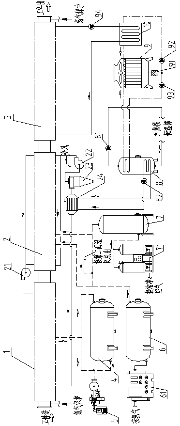
[0040] Such as figure 1 Described: a brazing system, including a ventilation section 1, an electric heating section 2, a cooling section 3, a vacuum system, a gas storage system, a constant temperature system, an air cooling system, a heat recovery circulation system and a water cooling system.

[0041] The vacuum system includes a vacuum tank 4 and a vacuum pump group 5 . One of the branches of the air outlet of the heat exchange section 1 is connected to the air inlet of the vacuum tank 4, and the other branch is connected to the vacuum pump group 5, which is also connected to the vacuum tank 4, and the vacuum tank 4 is coarse to the air intake of the ventilation section 1. Vacuuming, the vacuum pump group 5 performs fine vacuuming on the ventilation section 1, and the vacuum pump group 5 pre-evacuates the vacuum tank 4.

[0042] ...


PUM


Abstract

The invention discloses a braze welding system and a working method thereof. The braze welding system comprises a gas exchanging segment, an electric heating segment, a cooling segment, a vacuum-pumping system, a gas storage system, a constant temperature system, a heat recovering circulation system and a cooling system. The vacuum-pumping system comprises a vacuum tank and a vacuum pump unit. Onebranch of a gas outlet of the heat exchanging segment is connected with a gas inlet of the vacuum tank, and the other branch of the gas outlet of the heat exchanging segment is connected with the vacuum pump unit. The gas storage system feeds protective gas to the heat exchanging segment, the electric heating segment and the cooling segment. The cooling system comprises a water cooling system andan air cooling system. The constant temperature system is used for guaranteeing that the temperature of the heating segment is kept to be constant all the time when the heating segment is in a working state. The heat recovering circulation system is connected with the heat exchanging segment. The invention further discloses the working method of the braze welding system. According to the braze welding system and the working method of the braze welding system, on one hand, it can be guaranteed that workpieces to be welded can be welded in an assembly line manner, the braze welding process is carried out under the vacuum environment all the time, and the braze welding quality is effectively guaranteed; and on the other hand, the utilization efficiency of heat energy, the water resource andthe like can be greatly improved, and the production cost is reduced.

Description

technical field [0001] The invention relates to a brazing device, in particular to a brazing system and its working method. Background technique [0002] The existing brazing system mainly has the following defects: (1) The vacuuming speed is slow, and if the vacuuming is too long, the energy consumption of the vacuum pump unit will be greatly increased, and the service life of the vacuum pump unit will be reduced. Indirectly increase the cost; (2) It is impossible to realize the continuous welding of workpieces to be welded in the form of an assembly line, which greatly reduces work efficiency and wastes energy; (3) The cooling speed is slow, and one-time cooling is used, resulting in a large temperature difference on the surface of the workpiece, which cannot guarantee the quality of the workpiece. The hardness and the connection strength of the brazing connection surface greatly increase the defective rate; (4) The utilization rate of heat energy and water resources is lo...

Claims


Application Information

Patent Timeline
Patent Type & Authority Patents(China)
IPC IPC(8): B23K37/00
CPCB23K37/00B23K37/003
Inventor 张跃
Owner 远大可建科技有限公司
Learn More