Time domain heat reflection spectral measurement system

A measurement system and heat reflection technology, applied in the direction of color/spectral property measurement, measurement device, material analysis by optical means, etc., can solve the problems of high cost, low signal-to-noise ratio, redundant system structure, etc., to reduce equipment cost, improve the signal-to-noise ratio, and the effect of efficient and accurate measurement

Active Publication Date: 2018-06-01
NANJING UNIV
View PDF8 Cites 8 Cited by
  • Summary
  • Abstract
  • Description
  • Claims
  • Application Information

AI Technical Summary

Problems solved by technology

However, nonlinear crystals have low optical elimination rate, high cost, and increase the difficulty of...

Method used


Image

  • Time domain heat reflection spectral measurement system

Examples


Embodiment Construction
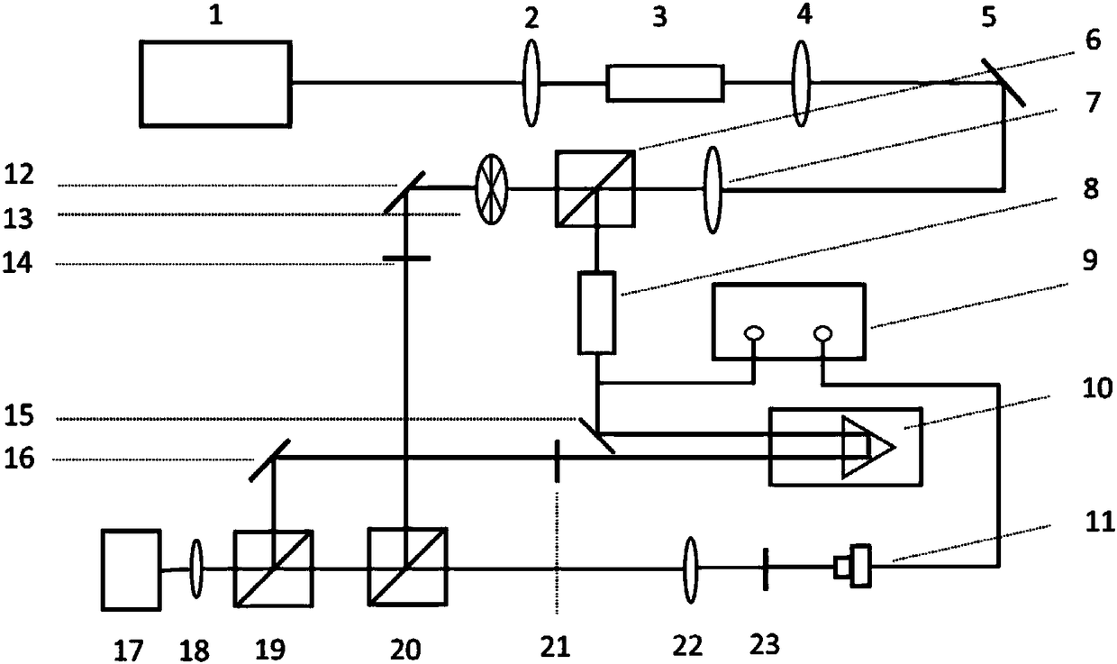
[0012] The technical idea of ​​a time-domain thermal reflectance measurement system provided by the present invention is: use three different optical filters and cooperate with a chopper to modulate the pump light and the probe light differently, and combine the two beams of light in the spectrum At the same time, the lock-in amplifier is used to extract the effective detection light signal, which avoids the influence of the pump light on the detection result, further eliminates the noise signal, improves the signal-to-noise ratio, and finally realizes accurate, stable and reliable measurement.

[0013] fit below figure 1 The present invention is described in detail, and it should be pointed out that the described examples are only for the purpose of enhancing the understanding of the present invention, and have no limiting effect on it.

[0014] Such as figure 1 As shown, the polarization laser 1 adopts a femtosecond fiber laser with a wavelength of 690nm-1020nm, a pulse wid...


PUM

PropertyMeasurementUnit
Wavelengthaaaaaaaaaa
Pulse widthaaaaaaaaaa
Poweraaaaaaaaaa

Abstract

The invention provides a time domain heat reflection spectral measurement system. The time domain heat reflection spectral measurement system is characterized in that a polarized pulse laser is incident into a first light-splitting device via a collimating lens after passing through an optical isolation system, and is divided by the first light-splitting device into two laser beams. which are in orthogonal polarization and respectively serve as pump light and detection light; the pump light passes through an electrooptical modulator, is incident into an optical retarder through a section reflecting mirror, is incident into a second light-splitting device via a short-wave pass filter and a third reflecting mirror in sequence, and is reflected by the second light-splitting device; and the detection light is modulated by an optical chopper, then, is reflected by a fourth reflecting mirror, is incident into a long-wave pass filter, is reflected and incident into the second light-splittingdevice via a third light-splitting device, and is merged with the pump light into a laser beam, and the co-linear light is focused onto the surface of a sample through an objective lens. According tothe time domain heat reflection spectral measurement system, non-linear crystals are not used, perfect separation of the pump light from the detection light on a spectrum is realized at a relatively low cost, and the signal-to-noise ratio is greatly increased.

Description

technical field [0001] The invention relates to solid thermal conductivity measurement technology, in particular to a time-domain thermal reflection spectrum measurement device. Background technique [0002] With the development of nanotechnology, the size of devices prepared by modern technology is getting smaller and smaller, and the problem of heat dissipation caused by thermal accumulation is becoming more and more obvious. At the same time, the continuous research and development of new thin film materials also urgently requires accurate characterization of the relevant properties of new materials. Only by accurately characterizing the heat transport properties of materials or microstructures can it be possible to further explore its heat transport mechanism. [0003] The time-domain thermal reflectance spectroscopy measurement system came into being, which is a transient measurement technology based on the pump-probe ultrafast optics detection principle to characteriz...

Claims


Application Information

Patent Timeline
IPC IPC(8): G01N21/27G01N21/25G01N21/01
CPCG01N21/01G01N21/255G01N21/27G01N2021/0106G01N2201/064
Inventor 卢明辉刘磊颜学俊陈延峰
Owner NANJING UNIV
Why Eureka
Try Eureka