Lever indicator
A lever table and lever technology, applied in the field of lever table, can solve the problems of affecting accuracy, increasing cost error, shortening the service life of lever table, etc., to achieve the effects of improving measurement accuracy, reducing errors and saving production costs
- Summary
- Abstract
- Description
- Claims
- Application Information
AI Technical Summary
Problems solved by technology
Method used
Image


Examples
Embodiment 1
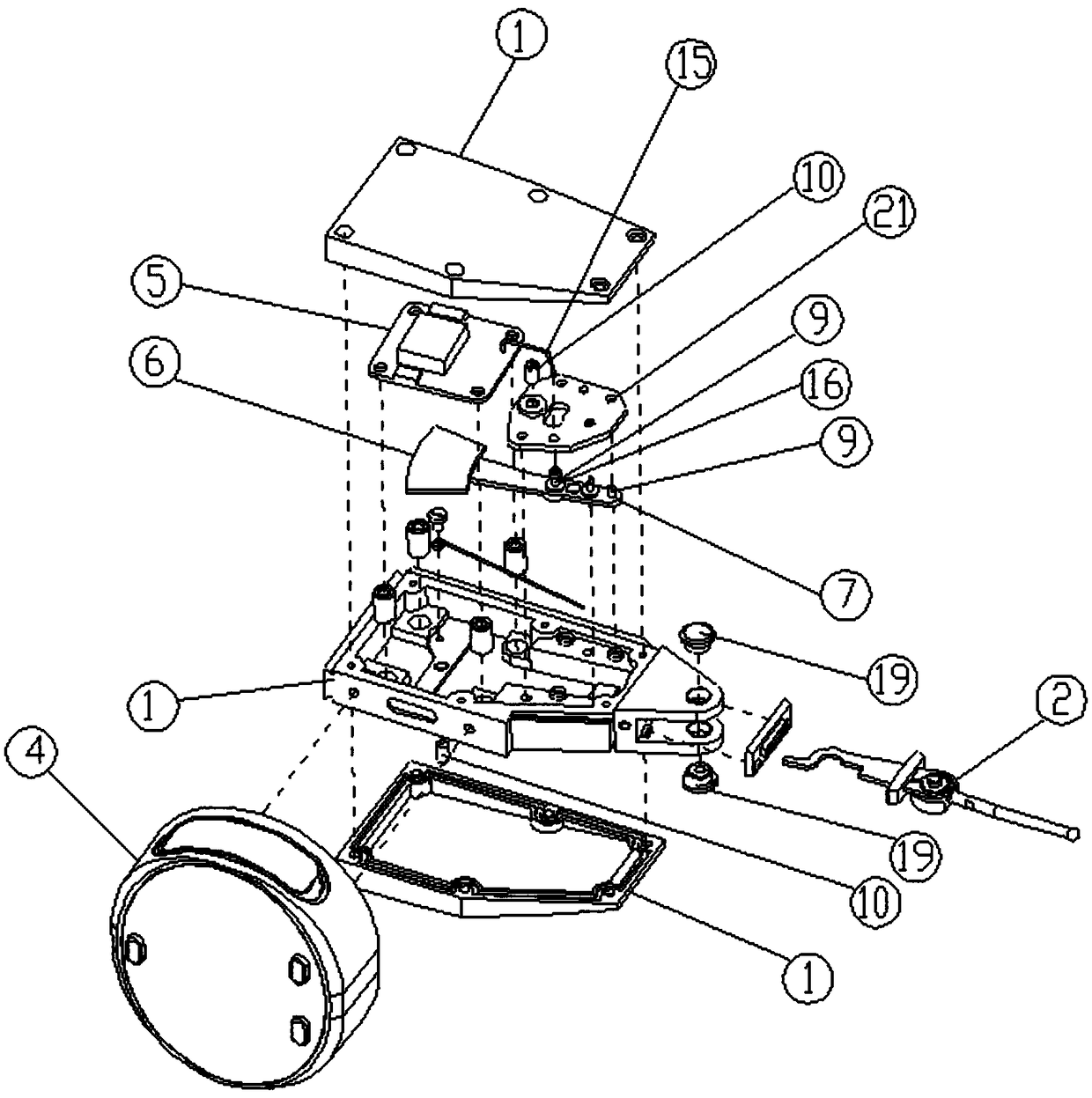
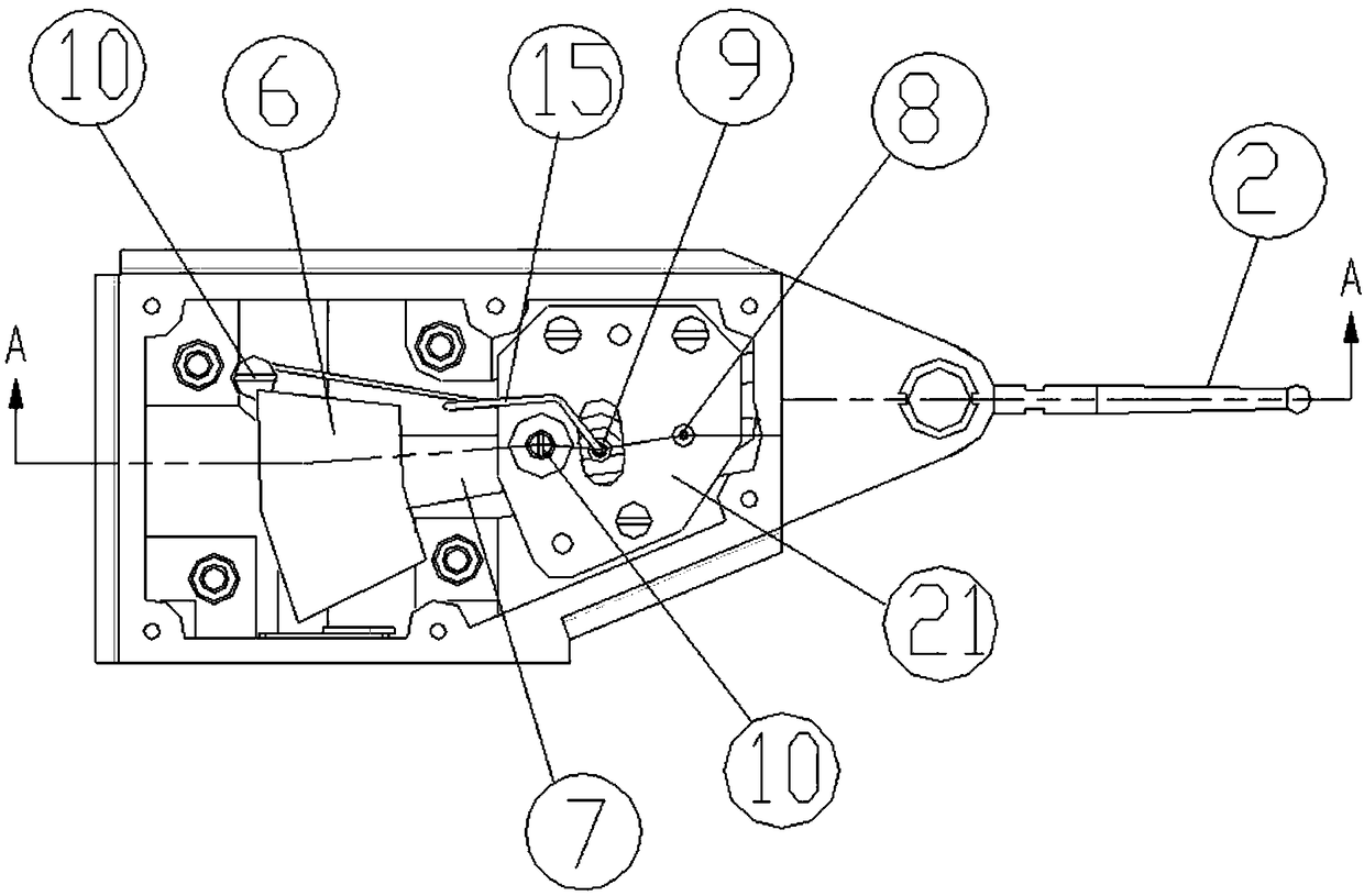
[0052] Such as Figure 1-4 As shown, a lever gauge includes a housing 1, a measuring lever, a displacement sensor and a single-chip microcomputer. The displacement sensor is inside the housing 1, the measuring lever is rotatably mounted on the housing 1, and its front end protrudes out of the housing 1 and is provided with a measuring contact 3, and the end extends to The inside of the housing 1 then oscillates synchronously with the displacement sensor for measurement. The single-chip microcomputer is in the housing 1 and corrects and calculates the measurement result through the signal generated by the displacement sensor swing. A liquid crystal display 4 for displaying the measurement result is also provided outside the housing 1 . The displacement sensor is any one of a capacitive grid sensor, a magnetic grid sensor or a CCD displacement sensor, and is composed of a fixed grid 5 and a sector-shaped movable grid 6 . The fixed grid 5 is fixed above the end of the measuring...
Embodiment 2
[0060] In this embodiment, the anti-sway mechanism is changed, and other structures are consistent with the first embodiment. Such as Figure 5-7 As shown, the anti-deflection mechanism includes two deep groove ball bearings 11 that limit the deflection of the rotation center shaft 8 in the horizontal and vertical directions; the two deep groove ball bearings 11 are located in the housing 1 and corresponding to the upper and lower positions of the rotation center shaft 8, the upper part and the lower part of the rotation center shaft 8 are respectively sleeved on the two deep groove ball bearings 11. Deep groove ball bearing 11 is due to its own structural characteristics, and its inner ring is fixed in the radial direction, that is, in the horizontal direction, and can slide up and down in the axial direction, that is, the vertical direction (upper and lower dead centers). Therefore, by fitting the first deep groove ball bearing 11 on the rotation center shaft 8, the deflect...
Embodiment 3
[0062] In this embodiment, the anti-sway mechanism is changed, and other structures are consistent with the first embodiment. Such as Figure 8-10As shown, the anti-deflection mechanism includes two thrust ball bearings 12 that limit the deflection of the rotation center shaft 8 in the horizontal and vertical directions; the two thrust ball bearings 12 are located in the housing 1 And corresponding to the upper and lower positions of the rotation center shaft 8 , the upper part and the lower part of the rotation center shaft 8 are respectively sleeved on the two deep groove ball bearings 11 . Thrust ball bearing 12 is due to its own structural characteristics, and its inner ring is fixed in the axial direction, that is, in the vertical direction, and can slide left and right (left and right dead points) in the radial direction, that is, the horizontal direction. Therefore, the first thrust ball bearing 12 is sleeved on the rotation center shaft 8 to limit the vertical deflect...
PUM
 Abstract
Description
Claims
Application Information
 - R&D
- Intellectual Property
- Life Sciences
- Materials
- Tech Scout
- Unparalleled Data Quality
- Higher Quality Content
- 60% Fewer Hallucinations
Browse by: Latest US Patents, China's latest patents, Technical Efficacy Thesaurus, Application Domain, Technology Topic, Popular Technical Reports.
© 2025 PatSnap. All rights reserved.Legal|Privacy policy|Modern Slavery Act Transparency Statement|Sitemap|About US| Contact US: help@patsnap.com