Hydrogen recovery and purification system and control method thereof
A control method, hydrogen technology, applied in the chemical industry, can solve problems such as unsuitable for hydrogen recovery and circulation
- Summary
- Abstract
- Description
- Claims
- Application Information
AI Technical Summary
Problems solved by technology
Method used
Image

Examples
Embodiment 1
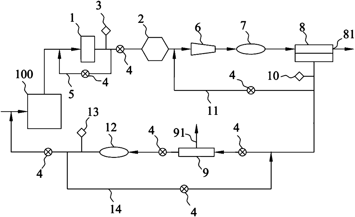
[0045] This embodiment provides a hydrogen recovery and purification system, such as figure 1 As shown, it includes an exhaust gas processor 1, a water removal device 2, a compressor 6, a first buffer tank 7, a first gas separation membrane group 8, a third hydrogen concentration sensor 3, a first hydrogen concentration sensor 10, and a second hydrogen concentration sensor. sensor 13;
[0046]The air inlet of the tail gas processor 1 is connected to the exhaust gas outlet of the industrial equipment 100, and the tail gas processor 1 purifies the hydrogen in the tail gas flowing through the tail gas processor 1 by spraying chemical reagents. The ammonia gas in the tail gas is removed by pouring the acidic liquid medicine, and the carbon dioxide and sulfur dioxide in the tail gas are removed by spraying lime water. The tail gas processor 1 is a prior art, and will not be repeated here. It should be noted that, according to the actual production situation, multiple tail gas trea...
Embodiment 2
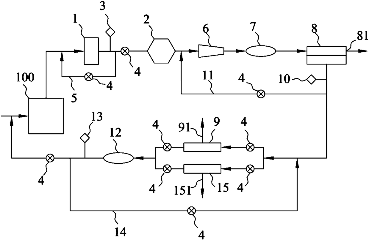
[0057] This embodiment provides a hydrogen recovery and purification system, such as figure 2 As shown, compared with Embodiment 1, the difference between this embodiment and Embodiment 1 is that the hydrogen recovery and purification system provided in this embodiment also includes a second hydrogen storage device 15, a second hydrogen storage device 15 and a first hydrogen storage device 9 has the same structure, the second hydrogen storage device 15 is provided with a fifth impurity gas exhaust port 151, one end of the second hydrogen storage device 15 is connected to the second buffer tank 12 through the control valve 4, and the other end is connected to the second buffer tank 12 through the control valve 4 and The connecting pipeline between the first hydrogen storage device 9 and the first gas separation membrane group 8 is connected, specifically, connected to the pipeline between the control valve 4 and the first hydrogen concentration sensor 10 . Thereby, when the fi...
Embodiment 3
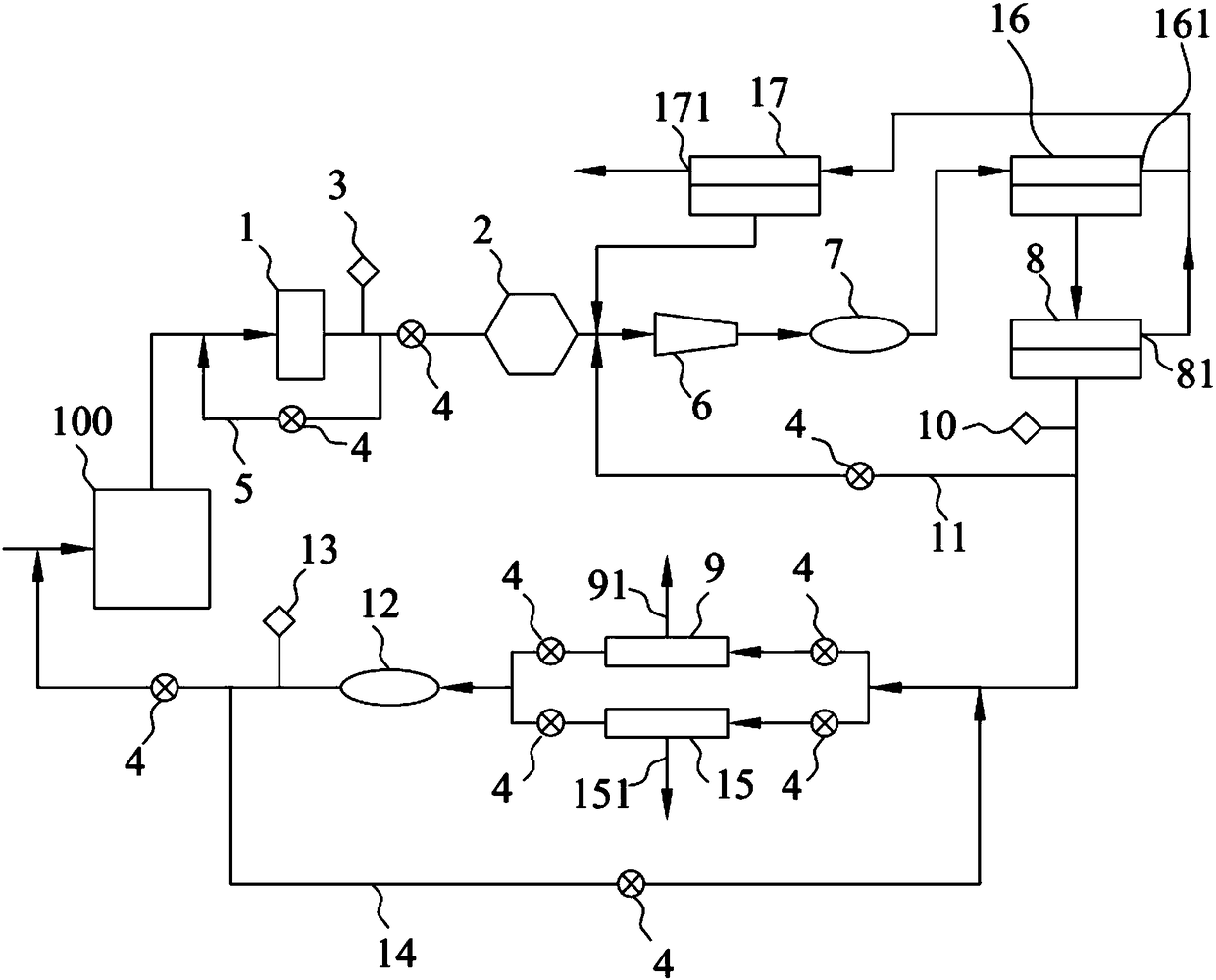
[0060] This embodiment provides a hydrogen recovery and purification system, such as image 3 As shown, compared with Embodiment 2, the difference between this embodiment and Embodiment 2 is that the hydrogen recovery and purification system provided in this embodiment also includes a second gas separation membrane group 16 and a third gas separation membrane group 17, the second gas The separation membrane group 16 and the third gas separation membrane group 17 have the same structure, and the second gas separation membrane group 16 and the third gas separation membrane group 17 are installed between the first buffer tank 7 and the first gas separation membrane group 8, specifically Yes, the inlet of the second gas separation membrane group 16 is connected to the first buffer tank 7, the exhaust port of the second gas separation membrane group 16 is connected to the inlet of the first gas separation membrane group 8, and the second gas separation The second impurity gas exhau...
PUM
 Abstract
Description
Claims
Application Information
 - Generate Ideas
- Intellectual Property
- Life Sciences
- Materials
- Tech Scout
- Unparalleled Data Quality
- Higher Quality Content
- 60% Fewer Hallucinations
Browse by: Latest US Patents, China's latest patents, Technical Efficacy Thesaurus, Application Domain, Technology Topic, Popular Technical Reports.
© 2025 PatSnap. All rights reserved.Legal|Privacy policy|Modern Slavery Act Transparency Statement|Sitemap|About US| Contact US: help@patsnap.com