
Valve body fixing device for valve machining

A technology of fixing device and valve body, which is applied in the direction of workpiece clamping device, measuring device, liquid tightness measurement using liquid/vacuum degree, etc. It can solve the problems of non-discoverable and repairable, convenient and fast processing, and fine processing, etc., to achieve Diversified fixing methods, convenient and fast processing, and convenient operation

Active Publication Date: 2018-06-01
高特控股集团有限公司
View PDF5 Cites 7 Cited by
  • Summary
  • Abstract
  • Description
  • Claims
  • Application Information

AI Technical Summary

Problems solved by technology

[0002] Fixing device is a kind of fixing device by clamping. It is usually used to fix and clamp the device during processing to prevent the device from moving during reprocessing, which will have a certain impact on processing and cause insufficient processing accuracy; existing There are certain disadvantages in the use of the valve body fixing device for valve processing. First, the air tightness of the processed valve cannot be tested, and it cannot be found and repaired in a more timely manner, and the processing cannot be made more refined. Secondly, it cannot pass The rotary table rotates, and the valve is processed, and the valve cannot be processed from multiple angles. Finally, the flange or valve body of the valve cannot be fixed differently, the fixing methods cannot be made more diverse, and the processing cannot be made It is more convenient and fast to meet people's needs. Therefore, we propose an uninterruptible power supply for construction sites

Method used


Image

  • Valve body fixing device for valve machining
  • Valve body fixing device for valve machining
  • Valve body fixing device for valve machining

Examples


Embodiment 1

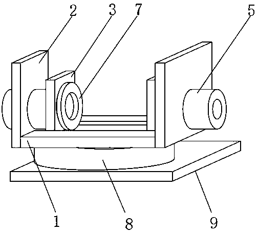
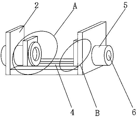
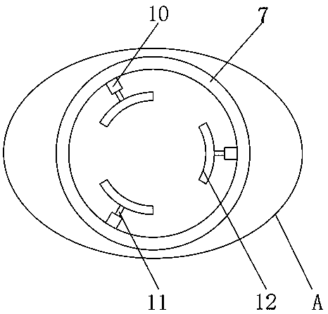
[0020] like Figure 1-4 As shown, a valve body fixing device for valve processing includes a stage 1 and a pressure gauge 13. The top outer surface of the stage 1 is provided with a fixed plate 2 near one side, and one side of the fixed plate 2 is provided with a movable Plate 3, the top outer surface of the stage 1 is provided with a sliding groove 4, one side of the fixed plate 2 is provided with a fixed shaft 5, and the inside of the fixed shaft 5 is provided with an air intake pipe 6, which can improve the airtightness of the processed valve. Detection can be performed in a more timely manner to find and repair, and the processing can be made more refined. A sealing ring 7 is provided on one side of the intake pipe 6, and a rotary table 8 is movably installed on the outer surface of the bottom end of the stage 1, which can pass through the rotary table 8. Rotate and process the valve, the valve can be processed from multiple angles, and the outer surface of the bottom end ...


PUM


Abstract

The invention discloses a valve body fixing device for valve machining. The valve body fixing device comprises an objective table and a pressure meter; a fixed plate is arranged on one side of the topend outer surface of the objective table, a moving plate is arranged on one side of the fixed plate, a sliding groove is formed in the outer surface of the top end of the objective table, a fixed shaft is arranged on one side of the fixed plate, an air inlet pipe is arranged in the fixed shaft, a seal ring is arranged on one side of the air inlet pipe, a rotating table is movably mounted on the outer surface of the bottom end of the objective table, and a containing plate is fixedly mounted on the outer surface of the bottom end of the rotating table. The valve body fixing device for valve machining is provided with the pressure meter, the air inlet pipe, the rotating table, the seal ring and the clamping plate, a machined valve can be subject to seal performance detection, multi-angle valve machining is carried out, machining is more convenient, a valve body or an abut-joint flange can be fixed, and the better use prospect can be achieved.

Description

technical field [0001] The invention relates to the field of fixing devices, in particular to a valve body fixing device for valve processing. Background technique [0002] Fixing device is a kind of fixing device by clamping. It is usually used to fix and clamp the device during processing to prevent the device from moving during reprocessing, which will have a certain impact on processing and cause insufficient processing accuracy; existing There are certain disadvantages in the use of the valve body fixing device for valve processing. First, the air tightness of the processed valve cannot be tested, and it cannot be found and repaired in a more timely manner, and the processing cannot be made more refined. Secondly, it cannot pass The rotary table rotates, and the valve is processed, and the valve cannot be processed from multiple angles. Finally, the flange or valve body of the valve cannot be fixed differently, the fixing methods cannot be made more diverse, and the pro...

Claims


Application Information

Patent Timeline
IPC IPC(8): B25B11/00B25H1/10G01M3/28
CPCB25B11/00B25H1/10G01M3/2876
Inventor 陈育玺
Owner 高特控股集团有限公司
Learn More